Single flat fold marker hydraulic assembly, Assembly instructions – Great Plains 2600-2S Assembly Instructions User Manual
Page 2
2
3000-3S and 2600-2S Marker Option 113-561M
2/28/2006
Great Plains Mfg., Inc.
Assembly Instructions
1.
Assemble the second marker section (#2) to the first section
(#1) with the 5/8" x 5 1/2" long bolt (#5), 5/8" lock nut (#4), 3/
8" x 2" long grade 2 shear bolt (#6), and 3/8" lock nut (#7).
The STOP BLOCK at outboard end of the second marker
section (#2) must be POSITIONED ON TOP as shown in the
illustration.
2.
Place the third marker section (#3) over the end of the
second section (#2) and insert 1" x 10 3/16" hinge pin (#9)
through the second and third section pivot. Secure the hinge
pin (#9) with the 1/4" x 2" long bolt (#17) and 1/4" lock nut
(#16).
3.
Bolt the chain bar weldment (#13) to the first marker section
(#1) with 3/8" x 3 1/4" long bolt (#11) and 3/8" lock nut (#7).
The chain bar weldment (#13) should pivot freely on the 3/8"
bolt (#11). Bolt the chain bar (#10) to the third marker sec-
tion with the 3/8" x 1 1/2" long bolt (#8) and 3/8" lock nut (#7).
The chain bar (#10) should pivot freely on the 3/8" bolt (#8).
Connect the marker chain (#15) between the chain bar
(#10) and chain bar weldment (#13) with 5/16" utility clevis-
es (#14). With the marker disk adjusted for seeding width
and the disk touching the ground, adjust the chain length to
remove the slack. The adjustment should be made at the
utility clevis (#14) nearest to the drill.
4.
The purpose of the 3/8" x 2 1/2" long full thread stop bolt
(#12) is to hold tension on the marker chain (#15) ONLY
when the marker is in the folded position. Therefore, the 3/8"
stop bolt (#12) and 3/8" lock nuts (#7) should be assembled
on the lift arm extension of section one (#1) so the head of
the stop bolt extends down as little as possible. After the
marker is bled and folded, adjust the stop bolt to remove the
slack from the chain. Refer to the "Marker Chain Adjust-
ments of the OPERATOR’S MANUAL.
5.
Assemble the marker transport mounts (#21) to the drill
wing sections with the 1/2" x 6 x 7 1/4" long u-bolts (#23),
1/2" USS flat washers (#24), 1/2" lock washers (#25), and
1/2" hex nuts (#26). The transport mounts (#21) should be
centered 58" in from the outer end of the box frame. Slide
the mount forward so its leading edge is about 3 13/16"
ahead of the front edge of the 6" x 6" box frame tube. The 3
13/16" dimension will position the mount close to the de-
sired transport location, but additional centering adjustment
may be needed when the marker is folded for the first time.
Refer to the "Marker Transport Carrier Adjustments" of
the OPERATOR’S MANUAL. The marker transport mount
(#21) contains a cutout for routing hydraulic hoses through
it. Disconnect the opener lift cylinder hoses at the inner
opener lift cylinder and reroute the hoses through the open-
ing in the marker transport mount. The marker hoses should
also be routed through the mount.
6.
Bolt the marker transport carrier (#22) to the transport
mount (#21) with the 1/2" x 2 x 3" long u-bolts (#27), 1/2"
lock washers (#25), and 1/2" hex nuts (#26). The marker
rest saddle is not centered on the marker transport carrier
(#22) and should be offset forward. The top surface of the
saddle that the marker rests on should be approximately 35"
above the top of the 6" x 6" box frame tube. The second
marker section should be parallel with the seed box lid and
centered in the saddle when the marker is folded. Adjust the
marker carrier height when the drills is folded for the first
time.Refer to the "Marker Transport Carrier Adjust-
ments" of the OPERATOR’S MANUAL.
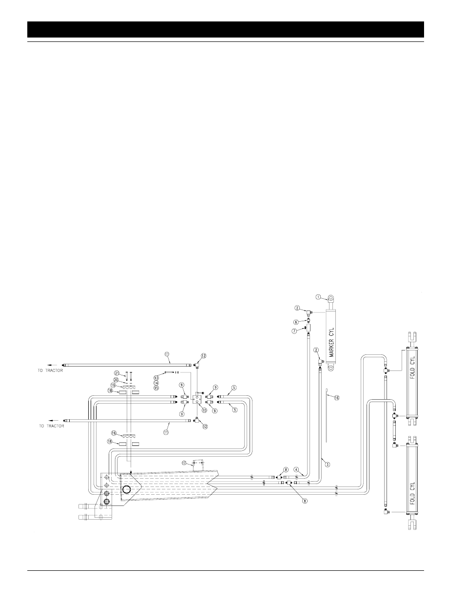
Single Flat Fold Marker
Hydraulic Assembly
Refer to Figure 2:
1.
Assemble elbows (#2) to the hydraulic cylinder ports.
2.
Assemble 3/8" MNPT adapter (#6) and needle valve (#7) to
the rod end elbow fitting.
Single Marker Hydraulics
Figure 2
15685