2 port receive leds, 3 port transmit leds, 4 a/b link leds – Cabletron Systems FDDI User Manual
Page 28: Port receive leds -2, Port transmit leds -2, A/b link leds -2
Chapter 4: Troubleshooting
4-2
7F06-02 FDDI SmartSwitch Interface Module User’s Guide
4.2
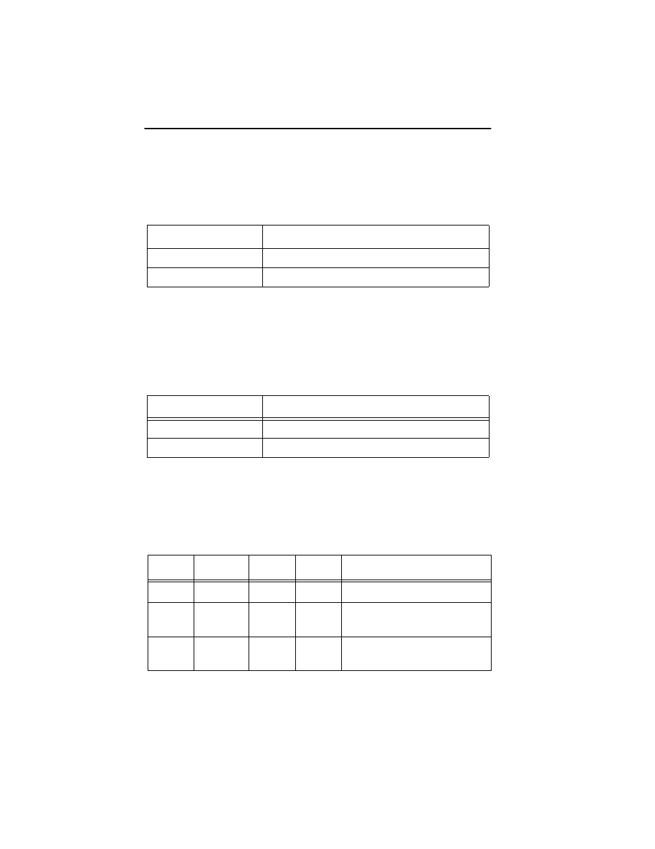
PORT RECEIVE LEDS
Table 4-1 indicates the state of the receive port.
4.3
PORT TRANSMIT LEDS
Table 4-2 indicates the state of the transmit port.
4.4
A/B LINK LEDS
Table 4-3 indicates the state of the A/B Link LEDs.
Table 4-1
Port Receive LEDs
LED Color
State
Yellow (Flashing)
Data activity (flashing to steady on indicates rate)
Off
No activity, port can be disabled or enabled
Table 4-2
Port Transmit LEDs
LED Color
State
Green (Flashing)
Data activity (flashing to steady on indicates rate)
Off
No activity, port can be disabled or enabled
Table 4-3
Link LEDs
A
P
S
B
State
Green
N/A
N/A
Green
Ports Enabled & Active
Green
Green
Off
Green
THRU A, MAC on Primary,
Secondary Bypasses Board
Green
Green
Yellow
Green
THRU A, MAC on Primary,
No MAC on Secondary
- 2E42-27R (164 pages)
- 6H122-16 (158 pages)
- 24 (35 pages)
- 9T427-16 (16 pages)
- bridges (132 pages)
- CSX200 (88 pages)
- 2208 (158 pages)
- SM-CSI1076 (69 pages)
- SEHI-22 (93 pages)
- 9T425-16 (40 pages)
- 6000 (180 pages)
- 1800 (448 pages)
- ESX-1380 (86 pages)
- DLE23-MA (202 pages)
- 2E43-51 (168 pages)
- 5000 (83 pages)
- 6H253-13 (62 pages)
- Lancast Media Converter 7000 (108 pages)
- SmartCell 6A000 (102 pages)
- 9G421-02 (12 pages)
- SEH-22 (56 pages)
- 9A000 (180 pages)
- SEH-24 (64 pages)
- 6E123-26 (184 pages)
- STS16-20R (258 pages)
- 2E43-27 (164 pages)
- Cabletron MicroLAN 9E132-15 (36 pages)
- 9F120-08 (28 pages)
- 9E428-36 (18 pages)
- Device Management Module Dec GigaSwitch (65 pages)
- ELS10-26TX (18 pages)
- MICROMMAC-22T (105 pages)
- CSX1200 (644 pages)
- 7H02-06 (36 pages)
- 150 (106 pages)
- 9F206-02 (10 pages)
- MMAC-Plus 9T122-24 (27 pages)
- SEH100TX-22 (52 pages)
- 7C03 MMAC (16 pages)
- 2H253-25R (64 pages)
- TRXI-42 (92 pages)
- 7C04 (150 pages)
- 2H22 (120 pages)
- 2000 (196 pages)
- 7C04 Workgroup (25 pages)