Preparation and setup – Great Plains 10 Gallon Stainless Tank Foam Marker Operator Manual User Manual
Page 12
Foam Marker
500-033M-A
4/21/2003
10
Preparation and Setup
Tandem Axle Sprayer / Foam Marker
Assembly Instructions and Set-Up
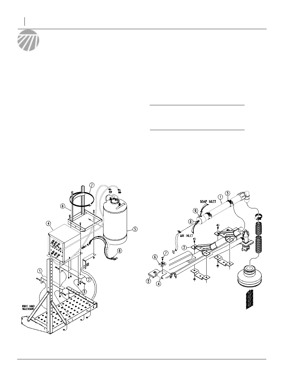
Refer to Figure 1
1.
Mount the support brackets (1) and (2) on the right
walkboard with 3/8" x 1" long bolts (3), flat washers,
and flange nuts required.
2.
Mount the foam marker box (4) and the foam tank
base (6) on the support brackets with 3/8" x 1" long
bolts and flange nuts required.
3.
Secure the foam tank (5) to the foam tank base (6)
with the hose clamp (7) provided.
4.
Attach a section of the clear hose from the hose
barb on the foam marker box (4) labeled "AIR TANK
IN" to the hose barb on the foam tank (5) that has a
white coupling. In a similar manner, attach a section
of the clear hose from the hose barb on the foam
marker box (4) labeled "FOAM TANK OUT" to the
black coupler on the tank. Attach the hoses with the
hose clamps provided.
Refer to Figure 2
5.
Attach the foam generator cylinder (1) on both boom
wings using the foam cylinder brackets (2), the 1/4"
screws and flange nuts. Make sure that the hose
barb (9) is on the top side of the cylinder. Use the
hose clamps (3) to attach the foam generator cylin-
der brackets.
Important: Mount the foam generator cylinders on
the back side of the boom. Failure to do so may
cause damage to the foam generator cylinders if the
boom strikes an object.
6.
In your foam marker kit there are some C-clips (4) to
help route the foam marker hose. These C-clips are
attached underneath the top side of the nozzle
check valve brackets (5). Assemble the T-clip (6)
and screw (7) to the C-clips. Loosen the nozzle
check valve brackets (5), slide the assembled
C-clips under the bracket and retighten the nozzle
check valve brackets. Assemble the C-clips uniform-
ly across the boom.
7.
Enclosed in the foam marker kit is some 1/4" clear
vinyl hose. Route a section of hose from the "AIR
LEFT" hose barb on the foam marker box to the
hose barb (8) that comes out the end of the foam
generator cylinder on the left boom wing. Route vinyl
Figure 1
Tandem Axle Foam Marker Assembly Illustration
11998
Figure 2
Foam Generator Assembly Illustration
11997