Setting variable rate gearbox – Great Plains NTA2007 Material Rate User Manual
Page 8
6
Great Plains Manufacturing, Inc.
VRG Air Drills
167-085B
2012-01-03
Setting Variable Rate Gearbox
The variable rate gearbox allows an infinitely variable
meter drive speed to attain a wide range of metering
rates. The ratio of gearbox input speed to output speed is
controlled by the position of a gearbox control arm. The
control arm has an indicator that points to a scale
marked in degrees. The Seed Rate Charts (or Fertilizer
Rate Charts) show the rate for each degree of arm
rotation.
Refer to the rate charts and set the variable rate gearbox
control arm to its scale setting for the target rate. With
the optional servo-controlled meters (Variable Rate Kit),
the rate is set via the console terminal.
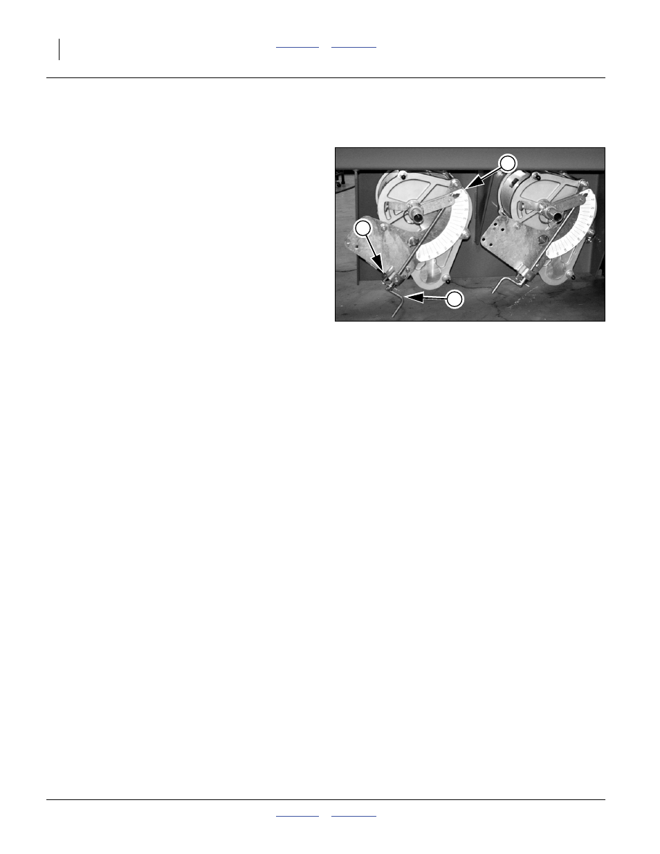
To adjust the Variable Rate Gearbox for each hopper:
Remove the hairpin cotter securing the gearbox
adjustment crank.
2.
Rotate crank until the control arm indicator points to
the scale setting that matches the rate from the
chart, or as determined by calibration.
3.
Re-insert the hairpin cotter.
Note: The variable rate gearbox operates optimally
between 30 and 70. If a material has charts for both
HIGH Range and LOW Range, the most consistent
results are obtained when the gearbox control arm
is set between 30 and 70. Settings below 20
degrees are not recommended. When the control
arm is set above 70 degrees, large movements of
the arm result in small changes in seeding rate.
Note: If you will be metering the same material from both
bins at the same time, use the chart entry for half
the target application rate. Do not use a half scale
setting - the effect of the variable rate gearbox
control arm is not linear.
Figure 6
Variable Rate Gearboxes
26306
1
2
3