Tank rinse and flush system – Great Plains TS1000 Trailer Sprayer Operator Manual User Manual
Page 22
Great Plains Mfg., Inc.
TS1000
20
7/6/09
TS1000 Trailer Sprayer 500-111M
1.
Drain the sprayer tank of any excess water or chemi-
cal. Dispose of or store chemical properly by instruc-
tions on the chemical label.
2.
Park the sprayer on a level, solid area.
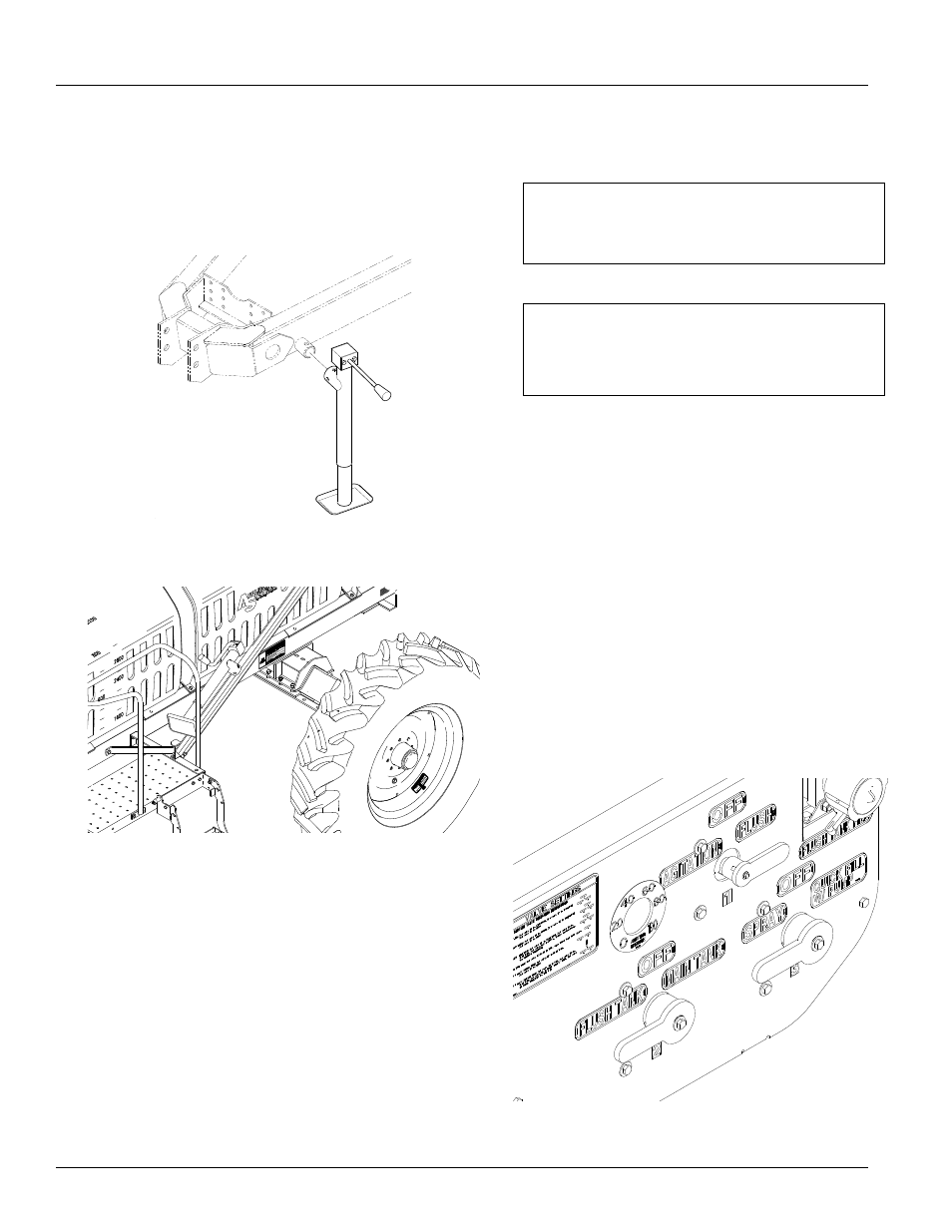
Refer to Figure 11 and 12
3.
Remove the jack from the transport position and move
to the parking position.
1. If the ground is soft, place a board or plate under the
jack to widen the ground contact area.
2. Extend the jack until the weight of the tongue is off the
tractor drawbar and is supported by the jack.
Figure 11
Jack In Parking Position
13811
3. Unplug the hydraulic lines from the hydraulic pump.
4. Remove the hitch pin and safety chain from the tractor
drawbar.
Tank Rinse and Flush System
The Tank Rinse and Flush is a factory installed feature that
will flush the tank and plumbing with clean water.The Tank
Rinse and Flush will use the fresh water in the 100 gallon
flush tank to rinse out the main sprayer tank in the field.
Refer to Figure 13
Before operation make sure the flush tank is filled with
fresh, clean water. To operate the Tank Rinse and Flush
option, refer to the following instructions:
1.
Completely empty the chemical in the main sprayer
tank by turning the agitation off the last pass and
spraying it out in the field.
2.
Make sure all boom valves and pump are turned off.
3.
Turn the agitation valve #1 (in the control panel) to
“FLUSH”, and rotate the flush tank valve #2 from
“MAIN TANK” to “FLUSH TANK”. Turn operation valve
#3 to “SPRAY”.
IMPORTANT: Refer to Tractor/Sprayer Hook-Up in
the “Assembly and Set-up” section on page 11
when preparing to hitch the sprayer to the tractor.
IMPORTANT: If the sprayer is being hitched up
and operated for the first time, it is important to fol-
low the safety, set up, adjustment, and operating
information in the front of this manual
Figure 12
Jack In Transport Position
20402
Figure 13
Control Panel
22672