Gang angle adjustment – Great Plains 1500TM Operator Manual User Manual
Page 21
Great Plains Manufacturing, Inc.
Preparation and Setup
17
12/12/2013
586-535M
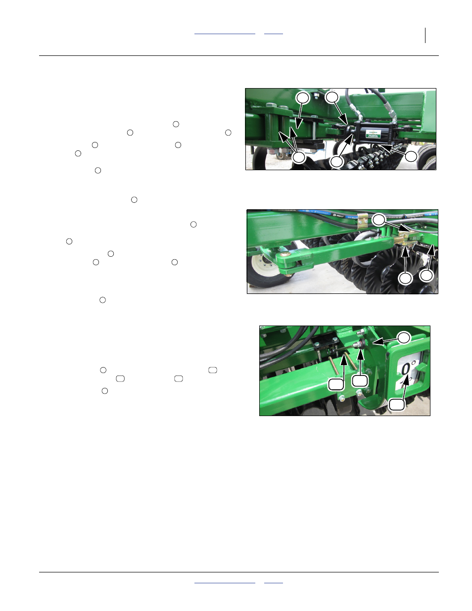
Gang Angle Adjustment
Note: Check gang angle adjustment when machine is new
and annually after, as wear may occur
11. With front gang adjusting cylinders
in the full retract
position the gang bar
should be 1/8” from tubes
.
12. If gang bar
is not 1/8” from tubes
loosen allen
screw
on clevis on rod end of cylinder (there are two
flat spots on rod to get wrench on to adjust) and shorten
cylinder rod
by turning cylinder rod to bring gang bar
closer and lengthen clevis to get cylinder to retract all
the way.
13. Re-tighten allen screw
when adjustment is made.
Refer to Figure 11
14. When the front gang adjusting cylinders
, have been
adjusted and are in the full retract position the rear gang
bar
should be parallel to back frame tube.
15. If rear gang bar
is not parallel to back frame tube,
remove pin
from turnbuckle end
and shorten turn-
buckle end by turning clevis to bring gang bar closer and
lengthen clevis to lengthen to get gang bar to retract all
the way.
16. Re-install pin
when adjustment is made.
17. When the front and rear gangs are adjusted and gang
angle cylinders are fully retracted then the gang angle
indicator will need adjusted.
18. Remove bolt
from either end of gauge link
and
turn threaded end
until indicator
reads 0 degrees.
19. Re-install bolt
to secure gauge link.
Figure 10
Front Gang Angle Adjustment
42251
4
2
3
1
5
1
2
3
2
3
4
5
4
Figure 11
Rear Gang Angle Rocker
42252
7
6
8
1
6
6
7
8
7
Figure 12
Gang Angle Indicator Adjustment
42253
10
11
12
9
9
10
11
12
9