Great Plains 7560 Series VII Field Cultivator-Rigid Hitch Operator Manual User Manual
Page 23
Great Plains Mfg., Inc.
Section 1: Assembly
2/01/2005
Series VII 7551-7560 Field Cultivator, Rigid Hitch 560-199M
21
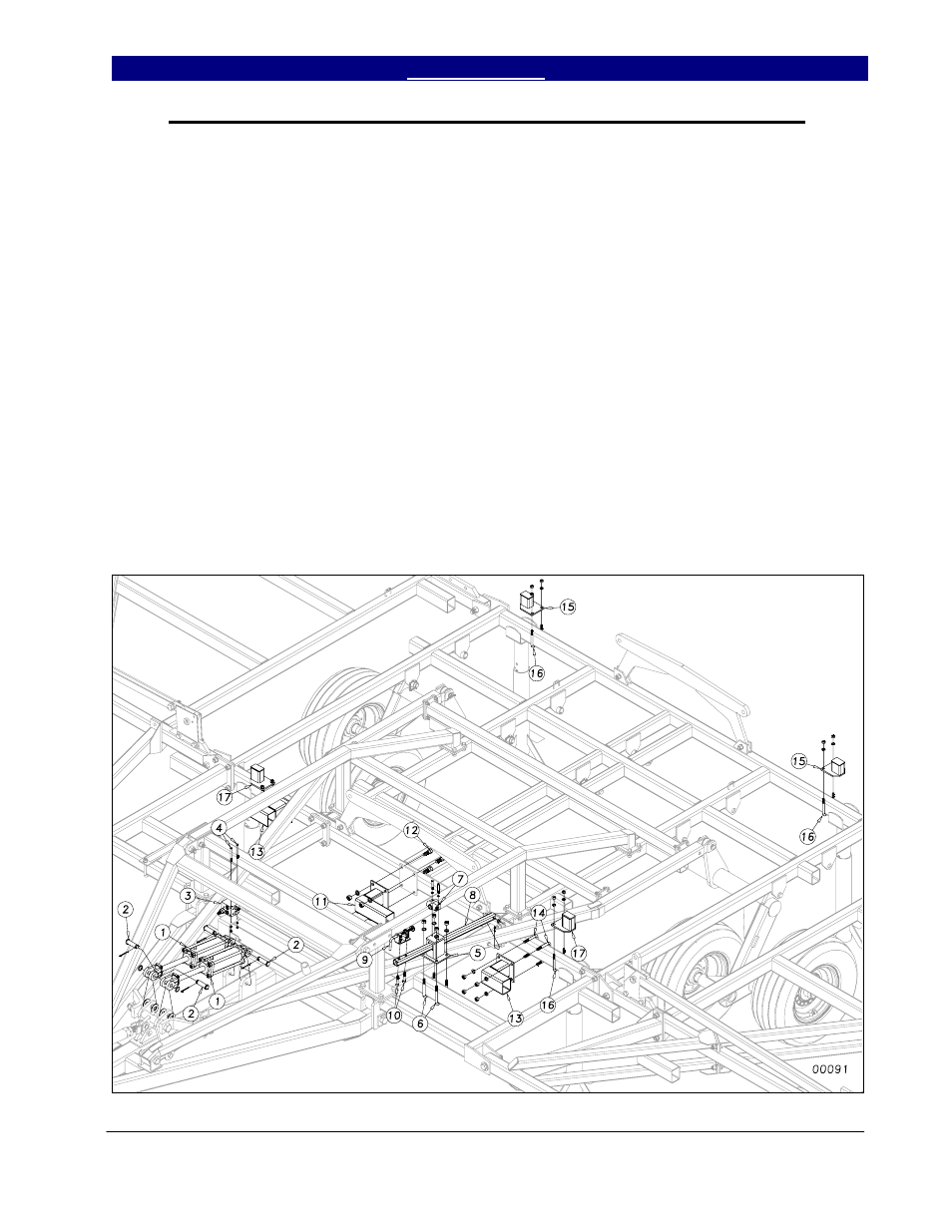
Center Lift Cylinder, Bolt On Stubs and Hydraulic Valves Assembly
Connect the two 3 1/2 x 8 rephasing
main lift cylinders (1) to the center hitch pole
as in Figure 8. Connect the rod ends to the
lugs on the H-bracket. Place a 1” flat washer
on each side of the lug on the H-bracket to
keep the hardened bushings from coming out.
Secure the cylinders with 1 x 3 1/2”
clevis pins (2), 1” machine washers and 3/16 x
2 cotter pins. Mount the rebound valve (3) as
shown with the V1 port to the front and top
using two 5/16 x 4 hex bolts (4) with lock
washers and hex nuts.
Install the depth stop mounting bracket
(5) to the center brace bar using two 5/8 x 3 x
5 1/2 u-bolts (6), lock washers and hex nuts.
Bolt the depth stop valve (7) on top of the
bracket using the 5/16 x 2 hex bolts with lock
washers. Insert the depth stop tube (8) into the
mounting bracket (5) and attach to the level
bar with 1/2 flat washer and 1/8 x 1 cotter pin.
Bolt depth stop assembly (9) onto the depth
stop tube (8) with two 1/2 x 2 1/2 hex bolts
(10) using 1/2” lock washers and hex nuts.
Bolt the center offset stub (11) to the
center frame with four 3/4 x 2 bolts (12) with
lock washers and hex nuts. U-bolt the 7”
offset stubs (13) to the center frame, as shown
in figure 8, using two 5/8 x 4 x 4 1/4 u-bolts
(14) with lock washers and hex nuts (see shank
layout drawing for proper placement).
U-bolt the 3 1/2” cylinder rest pads
(15) on the back bar using a 1/2 x 3 x 5 u-bolts
(16) with lock washers and hex nuts. U-bolt
the 4” cylinder rest pads (17) on the center bar
as shown, using a 1/2 x 3 x 5 u-bolts (16) with
lock washers and hex nuts (see shank layout
drawing for exact placement).
Figure 8
5/22/2008