4 disc units, 3 pro-active tines, 2 limit/tilt switch – Great Plains Simba 8-10m Press Operator Manual User Manual
Page 24
24 Simba 8-10m Press
608-205M-ENG
2013-03-08
4.4 Disc Units
(X-Press models
only)
The Simba X-Press features two rows of
discs which chop and mix the crop residue.
A disc spacing of 250mm ensures a fine tilth,
leaving the machine to pull straight making
the most efficient use of the power available.
The discs fitted to the X-Press are 500mm
in diameter (20”) and 6mm thick. They are
manufactured from heat treated chrome
boron steel which ensures excellent wear
resistance and enhanced working life.
Each disc is mounted on a Pro-Flex sprung
leaf linked to a track rod system. Gang
angles can be varied with ease and accuracy
using a shims on a hydraulic cylinder.
Adjustable angling of the discs (between
10°-25°) ensures penetration and stubble
mixing are achieved in one pass. Working
depth can be varied simply via shimmed
hydraulic cylinders. All this is achieved
without compromise to consolidation.
A level, evenly cultivated finish is maintained
by adjusting the balance of soil throw
between the front and rear discs.
Sprung Pro-Flex leaves offer protection
against damage as well as offering a degree
of contour following as they flex up and down
in work.
4.3 Pro-Active Tines
(CultiPress models only)
The Pro-Active tines are designed to move
soil and shatter clods to a greater degree
than traditional rigid leading tines. The abi-
lity to move in all directions (upwards and
sideways) allows them to clear stones and
other obstructions. They feature simple,
pinned tine depth adjustment for easy depth
variation.
Fig. 4.04: Pro-Active Tines
Fig. 4.05: Discs
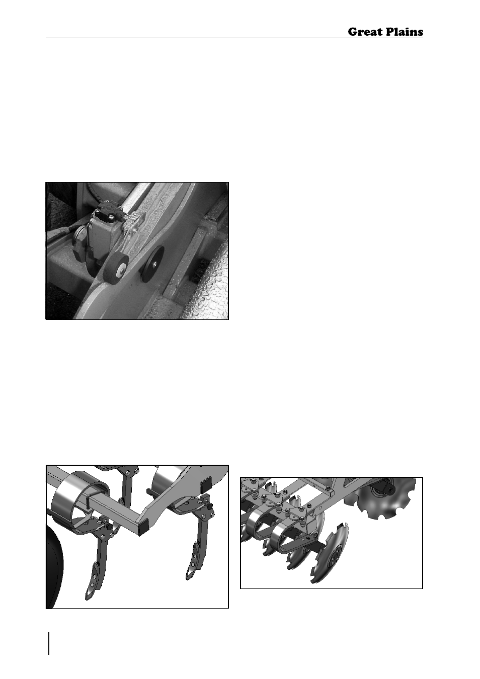
4.2 Limit/Tilt Switch
The Limit/tilt switch allows the operator to
adjust the pitch of the machine. If the machi-
ne is running nose low then the trip (profile)
can be moved forward (toward the tractor).
If the machine is running nose high then the
trip (profile) can be moved backward. When
setting this switch it is necessary to tilt the
machine fully rearward each time to reset
the limit switch.
Fig. 4.03: Limit/Tilt Switch
4. Adjustment / Operation