Great Plains 2420P Assembly Instructions User Manual
Page 4
120-299M
4/8/2004
Great Plains Mfg., Inc.
Veris Drive Option
4
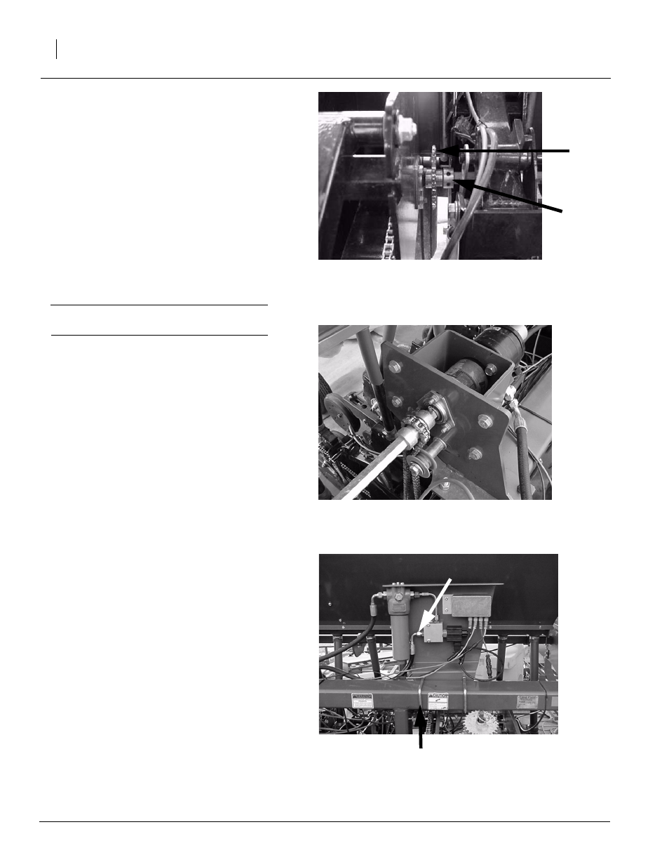
Refer to Figure 6
10. Loosen the lock collar on the line shaft
sprocket and pull each line shaft out until the
shaft allows access between the two openers
below the sprockets installed in step 5. Slide
each 36 tooth sprocket and lock collar onto
the shaft and return the shaft to its original po-
sition.
Note: For 7 1/2" spacing, slide the 36 tooth
sprocket tight against the bearing and lock the col-
lar in place with set screws.
For 10" and 15" spacing align the 36 tooth sprock-
et with the sprocket above it, and hold in place
with a lock collar on each side.
Important: Remember to retighten the lock col-
lars at the end of the drill.
Refer to Figure 7
11. Install both drive chains and tighten with the
idler on the front side of chain.
Refer to Figure 8
12. Install the control module on the top tube of 3-
point mainframe using 1/2” x 3" x 4" U-bolts.
Locate the module so that the inside U-bolt
measures 54 3/4" from the center of the frame
on 15’ drills and 68 1/4" on 20’ and 24’ drills.
Note: The marker storage post (if equipped) may
need to be moved out board on the frame to clear
the control module.
13. Connect the 28" hose from the control valve
block to the motor. Connect the cable from
drive motor encoder to the controller cable.
Note: All connectors are specific so no incorrect
connections can be made.
Hydraulic
hose to motor
Measure from center of frame
Figure 6
Line Shaft Sprocket
Figure 7
Drive Chain
Figure 8
Control Module
19973
19971
19974
36 tooth
sprocket
Lock collar
(7 1/2" spacing
shown)