Great Plains 2420P Assembly Instructions User Manual
Page 3
4/8/2004
120-299M
Great Plains Mfg., Inc.
3
Installation Instructions
15P
Bracket (center)
Spacing
LH
RH
7 1/2”
32 9/16”
47 1/2”
10'
32 9/16”
42”
15”
35”
45”
Twin Row
34”
47 1/2”
Twin Row*
34”
55”
*2003 Model Year S/N: 10682C and above
20P & 24P
Bracket (center)
Spacing
LH
RH
7 1/2”
47 1/2”
47 1/2”
10'
42”
42”
15”
47”
36”
Twin Row
47”
34”
Twin Row*
40”
34”
*2003 Model Year 20’ S/N: 7055B and above
24’ S/N: FF1194 and above
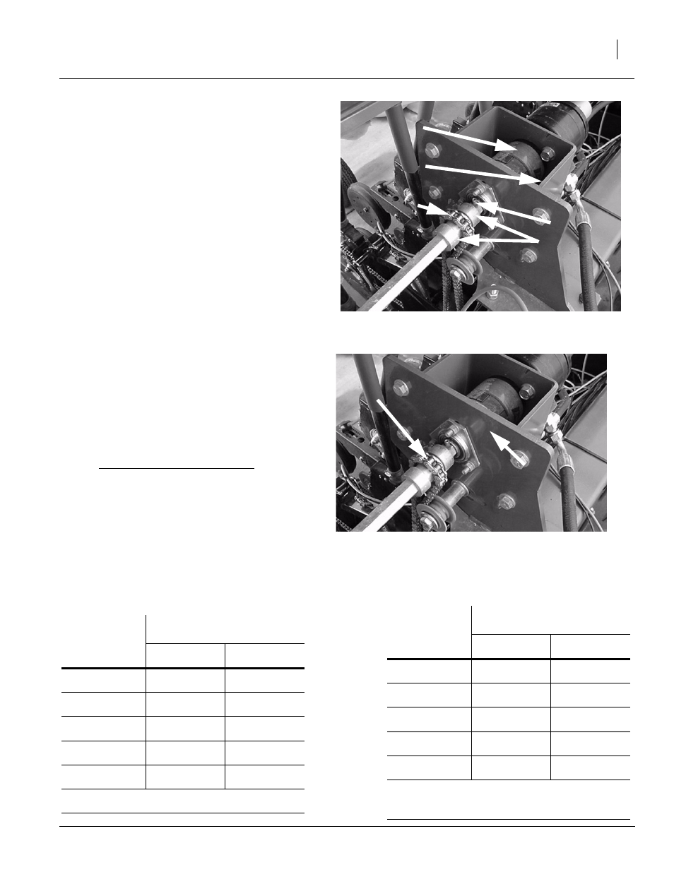
Refer to Figure 4
5.
Install one roll pin in the outside hole of the
shaft, then slide the 7/8” hex drive shaft part-
way through the left-hand drive bracket. Slide
all lock collars and 12 tooth sprockets on the
shaft then slide into other bearing. Tighten
bearings and push shaft to the left until the roll
pin contacts the left-hand bearing and install
the second roll pin.
6.
Slide 7/8" coupler with square key onto shaft
and leave loose Install rubber coupler. Install
motor adapter using 1/2” bolts provided in the
kit, leaving bolts loose.
7.
Install 1" bore coupler and square key onto
the motor. Install motor on the motor adapter.
Align couplers, making sure they can be eas-
ily slid together, then tighten adapter. After
tightening adapter, slide couplers together
and position them so they are centered in the
adapter, then tighten the coupler set screws.
Refer to Figure 5
8.
Line up the center of the left-hand and right-
hand sprockets in accordance with the table
below and tighten the lock collars.
Chain Center
Spacing
LH
RH
7.5"
2 1/2"
2 1/4"
10"
2 1/2"
2 1/4"
15"
2 1/2"
2 1/4"
Note: Measure from the face of the bracket to the
center of the sprocket (chain).
9.
Install chain idler tube, idlers and fasteners.
Shaft coupler
Motor adaptor
Sprocket
Roll pin
Lock collars
Face of
Bracket
Center of
Chain
Figure 4
Motor Shaft
19971
Figure 5
Sprocket Centering
19971