Install calibration handle stob, Assemble calibration crank, Replace jackshaft – Great Plains CALIBRATION CRANK Assembly Instructions User Manual
Page 7
10/4/2005
152-302M
Great Plains Mfg., Inc.
7
Installation Instructions
3P600/3P500/3P500V 152-305A & 152-306A Assembly Instructions
Install Calibration Handle Stob
Refer to Figure 1
1.
Choose a location on frame of drill to weld the
calibration handle stob.
NOTE: Be sure to choose an out of the way location
as the calibration handle stob stores the calibration
crank when it is not in use.
2.
Grind paint at location on frame where calibration
handle stob is to be welded.
3.
Weld calibration handle stob on frame.
4.
Repaint portion of frame.
Assemble Calibration Crank
1.
Place vinyl hand grip over calibration crank han-
dle.
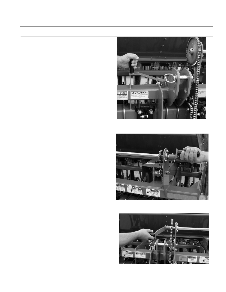
Replace Jackshaft
Refer to Figure 2
1.
Unscrew acremeter from jackshaft.
2.
Detach chain from sprocket on far right end of up-
per jackshaft. Remove sprocket from jackshaft.
3.
Detach chain from sprock on far left end of upper
jackshaft. Remove sprocket from jackshaft by
pulling jackshaft from drive assembly.
4.
Replace upper jackshaft with new jackshaft pro-
vided in kit. Reattach all sprockets and chains to
assembly.
23390
Figure 1
Calibration Crank on Storage Stob
23391
23393
Figure 3
Calibration Crank Location (Inside)
Figure 2
Calibration Crank Location (Outside)