Great Plains YP4025A-3215 32-Row 15-Inch Quick Start User Manual
Page 2
Quick Setup Guide for IntelliAg Model YP40 30” Twin Row Air Pro
11001-1542-200909
©2009 DICKEY-john Corporation
Specifi cations subject to change without notice.
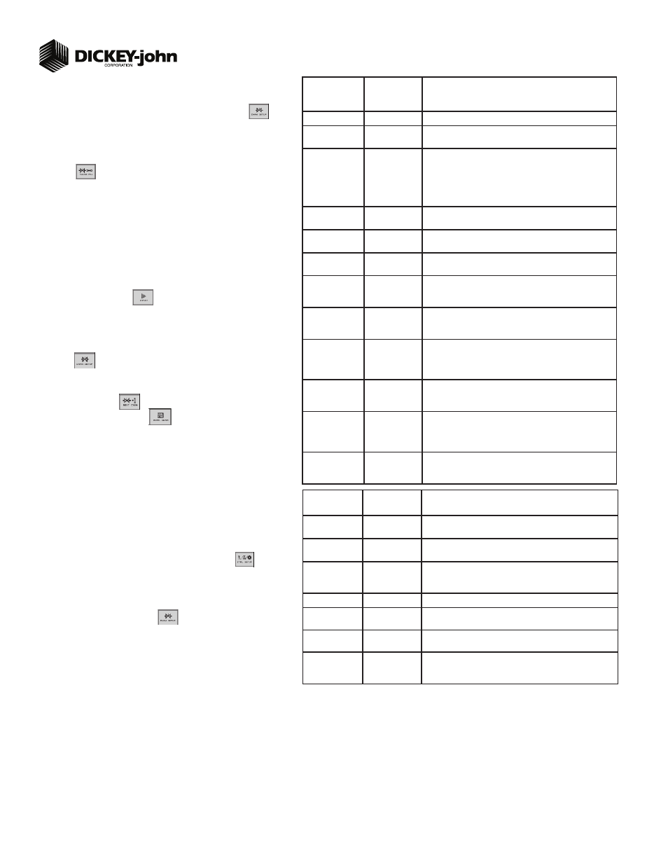
TABLE B2:
Planter Control
Setup
Default Value/
Value to Enter
Instructions/Defi nitions
Type
Planter Control
Set desired Channel Type as Planter Control.
Material Name
Displays only materials that have been confi gured for the channel
type.
Control Mode
AUTO
Auto is used in normal operating conditions calculating the rate
of how the system is running. Manual mode acts as an override
if application rate sensors are inoperable allowing the use of
increase/decrease buttons to set the fl ow rate for the control.
Refer to System Confi guration section of Operator’s manual for
additional information.
Drive Type
PWM
A hydraulic valve varies the oil fl ow to the motor proportioned to
the electric current supplied.
Drive Frequency
100 Hz
If not using a DICKEY-john supplied valve, see the manufacturer’s
specifi cations for drive frequency.
Input Filter
50
Feedback frequency fi lter for the control channel. DO NOT
CHANGE.
Gear Ratio
1.900
Specifys the actual ratio from the feedback sensor to the seed
meter shaft RPM. Number of revolutions the feedback sensor
turns in relation to one revolution the seed meter turns.
Sensor Constant
360
Sensor Constant establishes the number of pulses for one revolu-
tion of the feedback sensor. If a DICKEY-john application rate
sensor is used, the value should be set to 360.0.
# of Seed Rows
32
Entry of a specifi c number of seed rows for the control channel.
Row assignment is given a priority based on the channel and will
be assigned sequentially thereafter. Channel 1 is always assigned
to the fi rst set of rows, Channel 2 next set of rows, and so on.
Channel Width
480
Manual entry of the channel width for rows assigned to a specifi c
channel. Width calculation can be determined by # of planter rows
assigned to the channel multipled by the row spacing.
Precharge Time
+ 0.0
Typically used during startup conditions in the fi eld, a Precharge
time is a specifi ed length of time a control channel will operate
at the defi ned Precharge Ground Speed. Must be entered as a
positive (+) number.
Delay Time
- 0.0
Length of time before the control channel will start after the master
switch has been turned ON and the implement switch is in a
lowered position. Must be entered as a negative (-) number.
STEP 5B: Planter Control Channel Setup
(Controlled Hydraulic Drive)
At the Control Setup screen, press the Channel Setup button
.
Select Channel 1 and verify that the channel is set to Planter Control.
Enter desired values using Table B2 as reference.
After planter control setup, calibrate hydraulic valve by pressing the Valve Cal
button
.
Ensure implement is raised. With brakes locked and transmission in PARK
position, start engine.
Engage hydraulics and run engine at normal speed until hydraulic fl uid is at
operating temperature.
Verify point row clutches are turned ON.
Do NOT perform this step unless meters are installed in all locations
across planter row units or drive damage will occur.
Press the START button
. Turn the master switch to the ON position.
The valve calibration will immediately start. Keep the hydraulics engaged until
the calibration completes.
When the screen indicates calibration is complete, press the Channel Setup
button
to return to Channel 1 home screen.
Turn the master switch OFF.
To set up additional control channels (planter or fertilizer control), press the
Next Channel button
.
Press the Work Screen button
when channel confi gurations are
complete to return to the Main Work screen.
Once a control channel has been established as Planter Control, any new materi-
als established as Planter Control on the Material Setup screen will automatically
be added as optional materials for Planter Control channels on the Control Setup
screen.
1.
2.
3.
4.
5.
6.
7.
8.
9.
10.
11.
12.
2
STEP 6A: Material Confi guration Setup (Split Air Regulation)
It is recommended that when setting a control channel for split air, the
material name be created as “Air” to eliminate confusion between the actual
material and the control used.
At the Main Work screen, press the Control Setup button
.
Press Material button 16 for Split Air Control
Create Material Name as “Air”.
Enter desired values from Table C1.
Press the Channel Setup button
to proceed to the Channel Setup
screen.
1.
2.
3.
4.
5.
TABLE C1:
Material Setup
Default Value/
Value to Enter
Split Air Regulation
Instructions/Defi nitions
Type
Split Air Reg
Desired type of application control channel being used for a specifi c
material. CREATE MATERIAL NAME AS “AIR”.
Units
In H20
Oz in2
Automatically changes with the type of material application
selected. Changes units for target application.
Preset Method
Disabled
User-defi ned target rates can be confi gured and when enabled can
be adjusted from the Main Work screen using the Increment/Decre-
ment buttons.
Target Rate
2.00
Establishes the desired rate of application in inches of H20.
Max Rate
5.00
Maximum application rate in inches of H20.
Min Rate
1.00
Minimum application rate in inches of H20.
Inc/Dec %
5%
Percentage of change of the entered target rate applied each time
the Increment/Decrement button is pressed on the Main Work
screen.