Assembly, Hydraulic hose installation – Wheatheart In-Bin Super Sweep User Manual
Page 5
W
HEATHEART
- I
N
-B
IN
S
UPER
S
WEEP
1. A
SSEMBLY
A
LL
M
ODELS
1.1. H
YDRAULIC
H
OSE
I
NSTALLATION
IM5-R1
5
1. Assembly
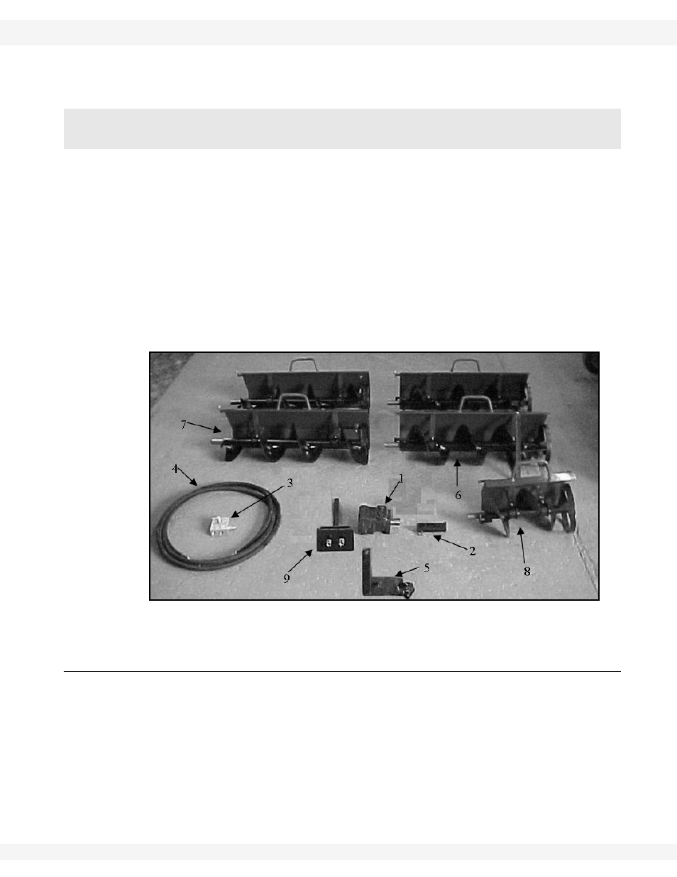
The In-Bin Sweep kit consists of (see Figure 1.1):
1. motor
2. motor
coupler
3. relief
valve
4. 2-16’
hoses
5. In-Bin
pivot
assembly
6. straight
section with a walking shoe
7. three plain straight sections
8. 1-15”
section
9.
In–Bin
Tower
Figure 1.1 In-Bin Super Sweep Kit (Total 11’3” Flighting in Kit)
1.1. HYDRAULIC HOSE INSTALLATION
1. Connect hydraulic hoses between orbit motor and relief valve.
2. Quick couplers may be used on pressure “P” and return (“T” for tank) fittings
of the relief valve.
Note:
System requires a minimum hydraulic source of 8 gpm at 1200 psi (see Figure
1.2 and 1.3).
Warning: Before continuing, please reread the safety information relevant to this section at the
beginning of this manual. Failure to follow the safety instructions can result in serious injury,
death, or property damage.