Assembly, Remote mount installation, Notice – Wheatheart Remote PowerSwing User Manual
Page 9
W
HEATHEART
- R
EMOTE
P
OWERSWING
2. A
SSEMBLY
A232, A233, A234, A235,
AND
A236
MODELS
2.1. R
EMOTE
M
OUNT
I
NSTALLATION
30664 R0
9
2. Assembly
The manual for the Hydraulic Powerswing is included with this kit and installing
the Remote Powerswing will follow all the same steps with a few additional steps
that must be completed first. Be sure to read this insert over PRIOR to assembly
to insure correct assembly order.
Note: If not using the 7-pin electrical connector supplied with the Powerswing, be sure
to note that the white wire of this cable is to be connected to a ground and the
black wire is to be connected to a 12- to 15-V source. It is strongly recommended
you get a qualified professional to ensure proper wiring.
2.1. REMOTE MOUNT INSTALLATION
The Remote Powerswing Retrofit is designed to allow the Hydraulic Powerswing
to function via remote. To install, follow the steps below and refer to Figure 2.1
and Figure 2.3.
1. Retrofit Only: Disconnect the hydraulic hoses from the old hydraulic valve.
2. Retrofit Only: Unbolt the old valve from the mount.
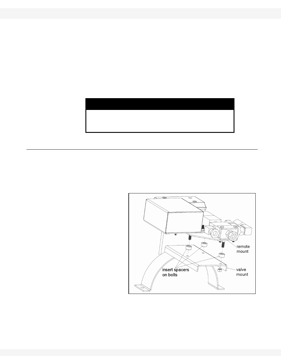
3. Place one of the
supplied spacers on
each of the three
bolts on the lower
side of the Remote
Retrofit mount (see
Figure 2.1).
4. Re-attach to the
original valve mount.
5. Connect the hydraulic
hoses to the new
valve.
NOTICE
Failure to connect the wires in polarity described will result
in unsafe operation and can cause undesirable effects such
as failure of the remote to function.
Figure 2.1