Monarch Instrument SPLS-5 Series User Manual
Page 7
4
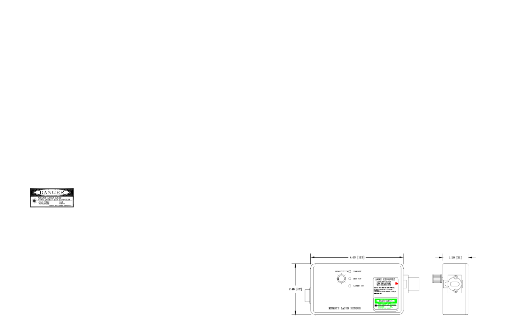
RLS-5P Remote Laser Sensor
Laser:
Visible red laser diode (670 nM), 5 mW peak power
Excitation Voltage: 4.8 to 8 Vdc @ 75 mA
Classification:
Normal Mode:
Class IIIa Laser Product
Setup Mode:
Class II Laser Product
Beam Divergence: 1.5 mrad typical
Beam Diameter:
4 x 0.6 mm
Laser Diode Life: 100,000 hours typical
Operating Range: Up to 50 feet [15 m] with reflective target
Min. Trigger Duration: 50 usec (equiv to 250,000 RPM)
Output:
5 to 0 Vdc TTL compatible pulse (open collector with
4.7 k pull up to 5 Vdc)
Connector:
Circular DIN Mak 4100 Socket
Indicators:
LASER ON, SET UP and ON-TARGET LEDs
Sensitivity Adjust: Single turn trimmer control knob on top panel
Modes:
Normal: Adjust sensitivity and distance from target
Set Up: Set up for reduced power (factory preset)
Dimensions:
Length: 5.5" [141 mm] including laser nosepiece
Body:
4.4" x 2.4" x 1.2" [113 mm x 62 mm x 31 mm]
Weight:
10 oz. [283 grams]
Mounting:
¼ -20 UNC Bushing in base of housing for tripod mount
or customer supplied bracket (can also be used to ground
the Remote Laser Sensor)
Temperature: Operating: -5
°
F to 122
°
F [-20° C to +50
°
C ]
Storage:
-25
°
F to 140
°
F [-30° C to +60
°
C ]
Humidity:
90% RH non-condensing
Controls
The Laser Sensor can detect small changes in reflective light due
to color or contrast changes, holes or slots in the surface or
reflectivity of the subject. The actual sensing distance varies, and
may be adjusted using the “Sensitivity” adjustment control on the
Laser Sensor. For maximum distance, it is advisable to use areas
of high contrast or reflective tape on the rotating object.
Operating the SPLS-5 as a triggering source
Mount the RLS-5P securely on a tripod or fixed surface that can be
moved for alignment purposes. For ease of alignment and reliability of
operation, locate the sensor as close to the target as practical (but not
within one inch). It is recommended that you aim the sensor at a
slight angle from perpendicular (approximately 15 degrees) to
ensure the sensor will detect only reflected pulses.
Turn the “Power” switch on the SPS-IM module to the ON position.
Open the shutter on the Laser Sensor. Observe that the LASER ON
LED illuminates.
CAUTION:
Avoid direct eye exposure to the laser beam.
Visually align the laser light with the target, ideally with the moving
equipment stopped. Start the equipment, and further adjust the manual
alignment and the “Sensitivity” control to maximize the brightness of
the green “TARGET” LED. This will be the condition of
optimum performance.
The pulse signal on the connector marked “Output” provides a sharp
leading edge for reliable and repeatable triggering of the connected
device. This output has a low impedance (50 ohms) and is capable of
11