Effects, Loop, Cv series block diagram 22 – Carver CV Series User Manual
Page 22: Cv series, Block diagram
Rev 04.08.021
- 22 –
Figure 17
Using Third Party Control Systems
Other manufacturers such as Crestron®, AMX® and PANJA® supply systems frequently used to provide a
centralized control platform for A/V Systems. A voltage ramp provided by one of these manufacturers, and
controlled by their system can be used to adjust level on the CV Series amplifiers. Apply a control voltage from
the external source of the desired control system to the “Remote Level” input terminal. This voltage may be
applied to either or both of the CV1 and CV2 input terminals. Connect the control voltage reference or common to
the RTN contact on the “Remote Level” input terminals. The –1dB per 50mV control characteristic mentioned
above applies in this application, as well. Externally supplied control voltages should not exceed 15VDC with
respect to the RTN terminal. Voltages in excess of 15VDC could possibly damage the “Remote Level” input
circuitry.
Note: Voltages in excess of 5V applied to CV1 or CV2 will not result in attenuation greater than 100dB.
Note: You should keep in mind that the front panel level adjustments act as master level controls when
using the remote level.
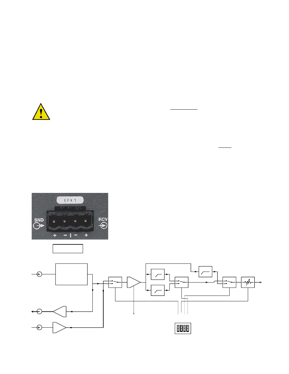
Effects Loop
When using the Effect Loop “EFX” to daisy chain signals to another amplifier, we recommend that you connect
the unbalanced “SND” Terminals of the effects loop to the next amplifier’s input module, do not use the “RCV”
terminal of the “EFX” loop. If daisy chaining to multiple amplifiers this should prevent the loss and degradation of
the signal as the number of the daisy chained amplifiers grows. (See Figure 16)
By connecting the amplifier in this manner, you can also take advantage of the effects loop as a signal processing
loop. Note that the signal from the original input to the first amplifier is delivered to the “SND” terminal of the
“EFX” loop as an unbalanced output. From there it can be split to go to the input module of another amplifier as
well as back into the “EFX” loop. The next amp receives a clean signal except for any processing that may have
occurred in the previous amplifier.
The “RCV” terminal of the “EFX” loop should only be use when the effects
loop is being used to accommodate outboard signal processing. This signal
should be local to the amplifier. The quality of the “differential” amp in this
feature is such that if long signal paths are used loss of signal quality should
be expected. If signals are being sent to the amplifier over a long distance,
we recommend that you use the amplifier’s input module, which offers
greater common mode noise rejection.
CV Series
CV Series
CV Series
CV Series
Block Diagram
EFFECTS
SEND -
ALW AYS
HOT!
EFFECTS
RECEIVE
SIG NAL
INPUT
Master Level,
Remote Level
Control Voltag e
Input
electronic
sw itch
VCA Section
electronic
sw itch
80Hz HPF
con figuration
DIP switch
EF
X
I
N
ON
C
L
IP
OF
F
OU
T
INPUT MODULE
120Hz HPF
17Hz HPF
80
H
z
OF
F
ON
H
P
120H
z
CV AMPL IFIER
SIG NAL PROCESSING BL OCK DIAGRAM
Heil 11.21.00
ONE CHANNEL SHOW N
electronic
sw itch
Signal to
Amp Output
Stage