Quoizel DE8961IB Devon User Manual
Quoizel Lighting
6 Corporate Parkway
Goose Creek, SC 29445
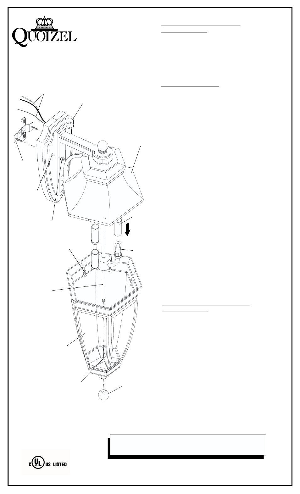
1. Before beginning fixture assembly / installation
carefully unpack and identify all parts referring
to illustration.
2. Turn power to the installation point
.
3. Locate the CROSSBAR and attach to WALL
MOUNTED OUTLET BOX with (2) OUTLET
BOX SCREWS (not supplied).
4.
OFF
Make the connections: (Quoizel recommends 2
people for this step). With the help of another
person, position the fixture in front of the wall
mounted outlet box. Connect the fixture GROUND
WIRE to the HOUSE GROUND WIRE. Proceed to
attach both to the CROSSBAR with GREEN
GROUND SCREW. Using wire connectors (not
supplied), connect the HOUSE WHITE WIRE to the
fixture WHITE SUPPLY WIRE; connect the HOUSE
BLACK (or RED) WIRE to the fixture BLACK
SUPPLY WIRE. Wrap all connections with
approved electrical tape. Carefully tuck all wires
into outlet box.
5. Position the FIXTURE BACKPLATE over the outlet
box so that the (2) MOUNTING HOLES in
backplate are aligned with (2) MOUNTING STUDS
on CROSSBAR. Pass BACKPLATE over
MOUNTING STUDS. Be sure there are no trapped
or pinched wires. Locate the (2) LOCK BALLS and
thread onto ends of MOUNTING STUDS. Tighten
until secure.
6. Refer to enclosed IS-727 for weather proofing
instructions.
7. Locate the SOCKET COVERS (amount depends
on style purchased) and place over SOCKETS.
Install bulbs referring to fixture markings and/
or labels for maximum wattage.
8. Locate the LOWER CAGE ASSEMBLY and
pass the LOWER STEM through the MOUNTING
HOLE at bottom of assembly. Position the top of
the assembly into the underside of FIXTURE
COVER. Secure assembly to fixture by threading
FINIAL onto the end of LOWER STEM. Hand
tighten until snug.
10 . Restore power to installation point.
1. Turn power to fixture OFF.
2. Remove FINIAL from bottom of fixture and
carefully remove LOWER CAGE ASSEMBLY.
3. Place the assembly on level work surface and
remove broken glass wearing safety glasses and
glass.
4. Loosen and remove GLASS PANEL SUPPORT
CLIP and install new REPLACEMENT GLASS
PANEL. Re-install support clip to secure panel.
5. Re-install LOWER CAGE ASSEMBLY.
6. Restore power.
GLASS PANEL REPLACEMENT
INSTRUCTIONS:
CROSSBAR
SUPPLY / GROUND
WIRES
FIXTURE
BACKPLATE
FIXTURE
COVER
SOCKET
SOCKET
COVER
GLASS PANEL
SUPPORT
CLIP
LOWER
STEM
LOWER CAGE
ASSEMBLY
FINIAL
(2) LOCK BALLS
MOUNTING
HOLE
ASSEMBLY / INSTALLATION
INSTRUCTIONS:
IF IN DOUBT ABOUT ELECTRICAL INSTALLATION,
CONSULT A LICENSED ELECTRICIAN!
IS-835
3.01
MOUNTING
HOLE
GENERIC ILLUSTRATION