Quoizel MCRM1716PN Ruckman User Manual
Warnings and cautions, Package contents, Hardware contents
Quoizel, Inc.
6 Corporate Parkway
Goose Creek, SC 29445
Customer Service
Phone 631.273.2700
Fax
631.231.7102
Tools Required: Flathead screwdriver, Phillips screwdriver, pliers, wire cutters, wire strippers, electrical tape,
safety glasses.
Estimated Assembly Time: 30-45 minutes
Preparation: Identify and inspect all parts before beginning installation. Check package content list and diagrams
below to be sure all parts are present. If any parts are missing or damaged, do not attempt to assemble, install, or
operate the fixture. Contact customer service for replacement parts.
Warnings and Cautions
1of2
Assembly Instruction Sheet #IS-MCRM1716PN
For Style MCRM1716PN
Bulb Recommended: (3) Medium Base 60W Maximum, Alternate bulb (3) 13W CFL
6 CORPORATE PARKWAY
GOOSE CREEK SC 29445
www quoizel com
,
.
.
.
Thank you for purchasing a Quoizel product.
Need assistance with parts or assembly? Call Quoizel customer service at 1-631-273-2700
or visit us on-line at
2014 QuoizelInc.
April2014
Turn off electricity at circuit breaker or main fuse box before installation. Consult a licensed electrician if in doubt.
These instructions are provided for your safety. It is very important you read them completely before installing the fixture. We strongly
recommend that a licensed, professional electrician perform the installation.
Disconnect fixture from power source before replacing bulbs. Make sure bulbs are given sufficient time to cool before removal. Do not subject
glass parts to any shock while in operation or shattering may result.
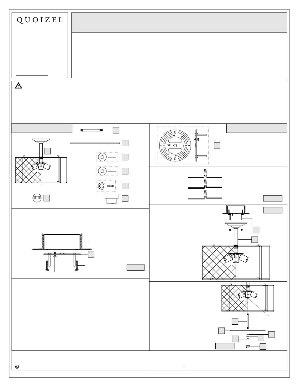
Package Contents
A
B
Fixture Body
x 1
Lock Ball
x 2
STEP 1
Install Crossbar
-
.
.
A. Attach the Crossbar Assembly (AA) to the Outlet Box with the head
of the Green Ground Screw facing you. Secure it with Outlet Box
Screws (not included)
Tighten until snug
Figure 1
Outlet Box
Outlet Box Screw
(not included)
Green Ground Screw
AA
Hardware Contents
AA
Crossbar Assembly
x 1
GND
2.4mm
13Ga
QUOIZEL
R
White wire
from supply
Ribbed side wire
from fixture
Black wire from
supply (or Red)
Smooth side wire
from fixture
Ground wire
from supply
Ground wire
from fixture
Figure 2
STEP 2 - Wire Connections
A. Use standard wire connectors (not included) to make all wire
connections. (Connectors are not included with fixture.) Strip and
prepare wire ends according to instructions supplied with
connectors.
B. Connect White Supply Wire from the Outlet Box to Ribbed side
Wire from fixture.
C. Connect Black (or Red) Supply Wire from the Outlet Box to Smooth
side Wire from fixture.
D. Connect Ground Wire from the Outlet Box to Ground Wire from
fixture.
E. Twist connectors until wires are tightly joined together.
F. Wrap each connection with approved electrical tape and carefully
stuff all the connected wires into the Outlet Box.
STEP 3
Attach Fixture Body to
Mounting Screw
-
A. Place the Ceiling Canopy of the
Fixture Body (A) over the
Mounting Screws and secure
with Lock Ball (B). Hand tighten
until snug.
Figure 3
J
Mounting Screw
Ceiling Canopy
A
C
Stem
x 1
D
Diffuser
x 1
E
F
Rubber
Washer
x 1
Flat
Washer
x 1
G
Hex Nut
x 1
H
Finial
x 1
STEP 4
Attach Diffuser to
Fixture
-
A. Thread have bead end of Stem
(C) into the Hex Coupling. Hand
tighten until sung.
B. Place the Diffuser (D), Rubber
Washer (E) and Flat Washer (F)
over the Stem (C), secure with
Hex Nut (G), hand tighten until
sung.
C. Thread Finial (H) onto the Stem
(C), hand tighten until sung.
Figure 4
Hex Coupling
C
D
E
G
H
F