Quoizel PCAT1617C Platinum Collection Avanti User Manual
Page 2
2of2
Thank you for purchasing a Quoizel product.
Need assistance with parts or assembly? Call Quoizel customer service at 1-631-273-2700
or visit us on-line at www.quoizel.com
2014 QuoizelInc.
January2014
PCAT1617C
PART NUMBER
G3819MR
G3846MR
G3847SH
NOTE: ALL DIMENSIONS ARE ROUNDED UP TO THE NEAREST 1/2
"
REPLACEMENT PART DESCRIPTION
MIRROR GLASS 15.5"D
MIRROR GLASS FLAT (BOTTOM) 16.5"D
SHADE ETCHED GLS PAINTED INSIDE 13.5"D
REQ.
1
1
1
NO.
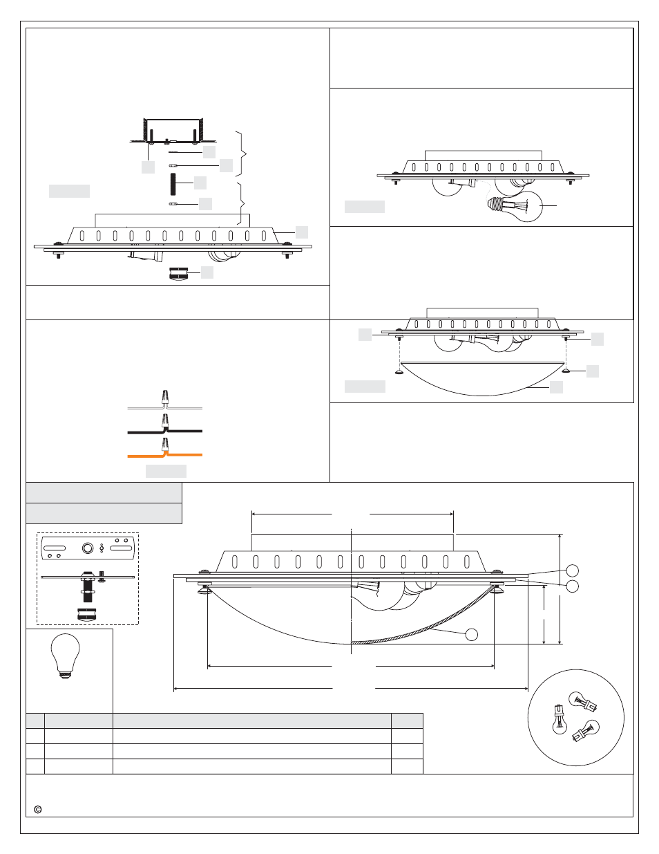
(3) 60W
Bulbs
(Not Supplied)
Medium
Base
1
2
3
FINISH: POLISHED CHROME
Thread this Hex Nut (CC) on just enough so the inside surface of the
Ceiling Canopy (A) rests against it. * You may have to trial fit the
Ceiling Canopy (A) one more times to insure this distance also. This
Hex Nut (CC) is needed here to prevent you from crushing down the
center of the Ceiling Canopy (A).
E. Refer to Step 4 for wire connections.
F. Attach the Ceiling Canopy (A) over the end of the Nipple (DD) and
secure with the Mounting Ball (EE). Hand tighten until snug.
TWO LIGHTS SHOWN FOR ILLUSTRATION PURPOSE ONLY.
AA
BB
CC
DD
CC
A
Step A
Step D
Figure 3
EE
STEP 4 - Wire Connections
A. Use standard wire connectors (not included) to make all wire
connections. (Connectors are not included with fixture.) Strip and
prepare wire ends according to instructions supplied with
connectors.
B. Connect White Supply Wire from the Outlet Box to Ribbed side Wire
from fixture.
C. Connect Black (or Red) Supply Wire from the Outlet Box to Smooth
side Wire from fixture.
White wire
from supply
Ribbed side wire
from fixture
Black wire from
supply (or Red)
Smooth side wire
from fixture
Ground wire
from supply
Ground wire
from fixture
Figure 4
STEP 6 - Install Shade
A. Attach the Shade (H) onto the Small Ring (C) and secure by
threading the Finial (I) onto the Lock Screw (D). Tighten gently until
snug.
Your fixture is now assembled and ready to use. Enjoy!
D
H
I
Figure 6
STEP 5 - Install Bulb
A. This fixture uses standard bulb with medium base. Maximum 60
watts.
B. Insert bulb and screw snugly into place.
Figure 5
Bulb
C
D. Connect Ground Wire from the Outlet Box to Ground Wire from
fixture.
E. Twist connectors until wires are tightly joined together.
F. Wrap each connection with approved electrical tape and carefully
stuff all the connected wires into the Outlet Box.
13.5” Dia.
16.5” Dia.
3”
5”
9” Dia.
2
1
3