Quoizel UST5003WT Union Station User Manual
Page 2
2of3
Thank you for purchasing a Quoizel product.
Need assistance with parts or assembly? Call Quoizel customer service at 1-631-273-2700
or visit us on-line at www.quoizel.com
2014 QuoizelInc.
February2014
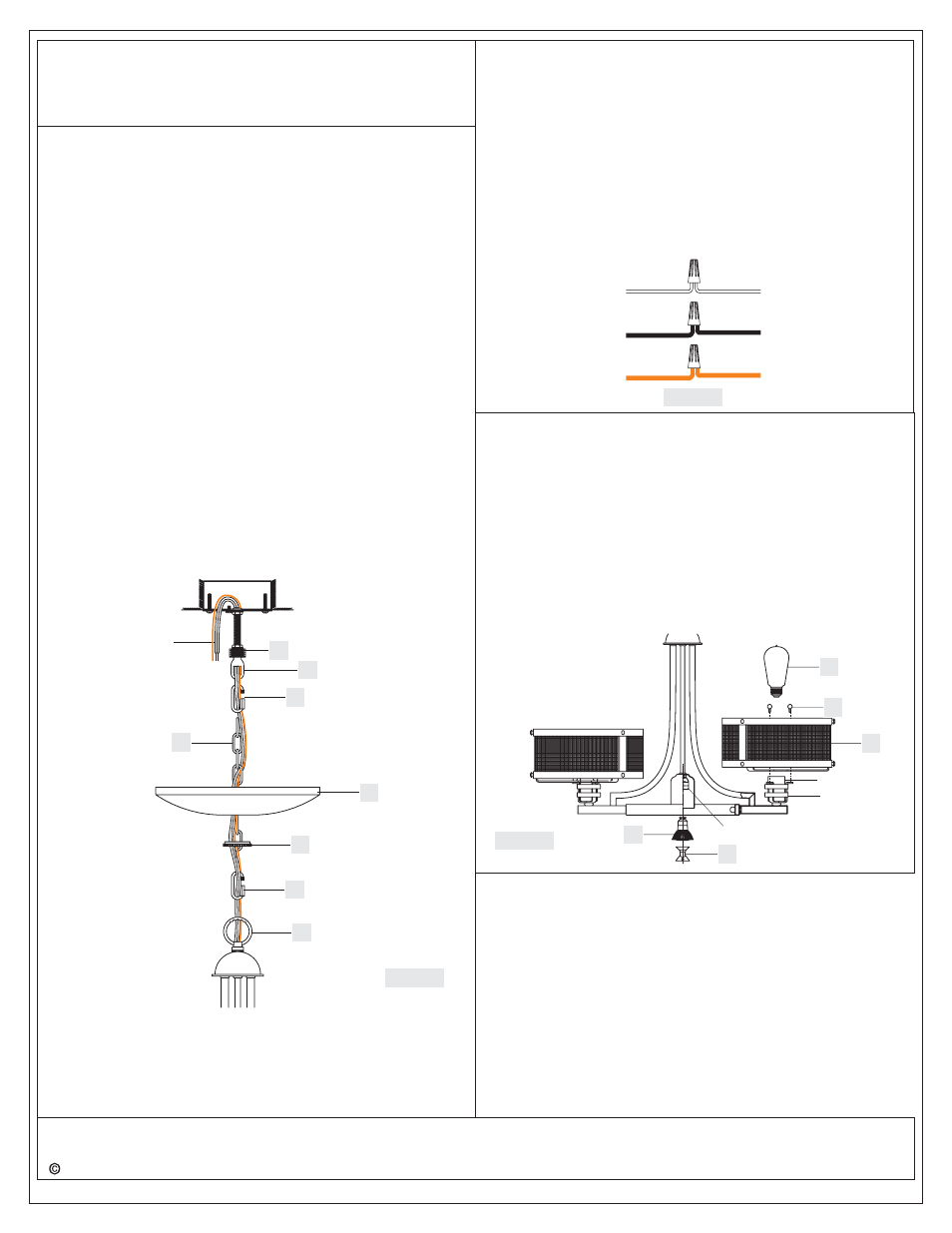
STEP 4 - Install Fixture Chain and Ceiling Canopy
A. Adjust the Fixture Chain (GG) to your desired length by removing
the links if needed.
Pliers is required for this step.
B. With the Fixture Chain (GG) not attached to the Fixture Loop (A) and
the Canopy Chain Loop (EE), pull the supply wires through the
Fixture Chain (GG) alternating links. After the wires are through the
Fixture Chain (GG), pull the Supply Wires and the Ground Wire
through the Canopy Lock Ring (FF) and the Ceiling Canopy (II) in
order.
C. Attach one end of the Fixture Chain (GG) to the Fixture Loop (A) with
one Quick Link (HH). Lift the fixture and Fixture Chain (GG) up And
Attach the other end of the Fixture Chain (GG) onto the Canopy
Chain Loop (EE) with another Quick Link (HH). The fixture will now
hang safely. Close the chain loop at the Ceiling Canopy Loop (EE).
D. Feed the Supply Wires and Ground Wire through the Canopy Chain
Loop (EE) and Nipple (DD) into the Outlet Box. Cut the wires leaving
approximately 8” of wire extending from the Outlet Box.
E. Refer to Step 5 for wire connections.
F. Raise the Ceiling Canopy (II) and Canopy Lock Ring (FF) up the
Fixture Chain (GG) and over the Canopy Chain Loop (EE). Tighten
the Canopy Lock Ring (FF) onto the Canopy Chain Loop (EE) until
tight.
Suggested chain length for Ceiling height :
8’ ceiling : use 8 links of chain and 2 quick links
9’ ceiling : use 17 links of chain and 2 quick links
10’ ceiling : use 25 links of chain and 2 quick links
*
Figure 4
DD
A
GG
II
Supply Wires
and Ground Wire
STEP 5 - Wire Connections
A. Use standard wire connectors (not included) to make all wire
connections. (Connectors are not included with fixture.) Strip and
prepare wire ends according to instructions supplied with
connectors.
B. Connect White Supply Wire from the Outlet Box to Ribbed side Wire
from fixture.
C. Connect Black (or Red) Supply Wire from the Outlet Box to Smooth
side Wire from fixture.
D. Connect Ground Wire from the Outlet Box to Ground Wire from
fixture.
E. Twist connectors until wires are tightly joined together.
F. Wrap each connection with approved electrical tape and carefully
stuff all the connected wires into the Outlet Box.
White wire
from supply
Ribbed side wire
from fixture
Black wire from
supply (or Red)
Smooth side wire
from fixture
Ground wire
from supply
Ground wire
from fixture
Figure 5
EE
FF
HH
HH
STEP 6
Install Shade and Bulbs
-
A. Place the Shade (F) onto the Shade Holder and secure with Small
Lock Screws (B). Hand tighten until snug.
B. This fixture uses standard bulbs 60W (supplied) with standard screw
base. Maximum 100 watts. Insert bulb and screw snugly into place.
C. This fixture uses a MR16 bulb 50W (supplied) with gu10 base. Put
the Plastic Suction Tool (H) onto the MR16-GU10 Bulb. Install the
Bulb into the Socket Base by aligning the pins on the MR-16 Bulb
with the keyholes in the Socket Base. Once they are aligned, gently
push the Bulb into the keyholes and twist the Bulb to lock it in place.
And then remove the Plastic Suction Tool (H) from the MR16-GU10
Bulb.
Your fixture is now assembled and ready to use. Enjoy!
Figure 6
Shade Holder
Socket
GU10 Socket
B
F
E
D
H
Adjust the Nipple (DD) to allow the Ceiling Canopy (II) to rest
against the ceiling when held in place by the Canopy Lock Ring (FF).
D. Remove the Canopy Lock Ring (FF) and the Ceiling Canopy (II).
Tighten the Hex Nut (CC) against the Crossbar (AA) to secure in
place.