Quoizel TF1784VB Tiffany User Manual
Page 2
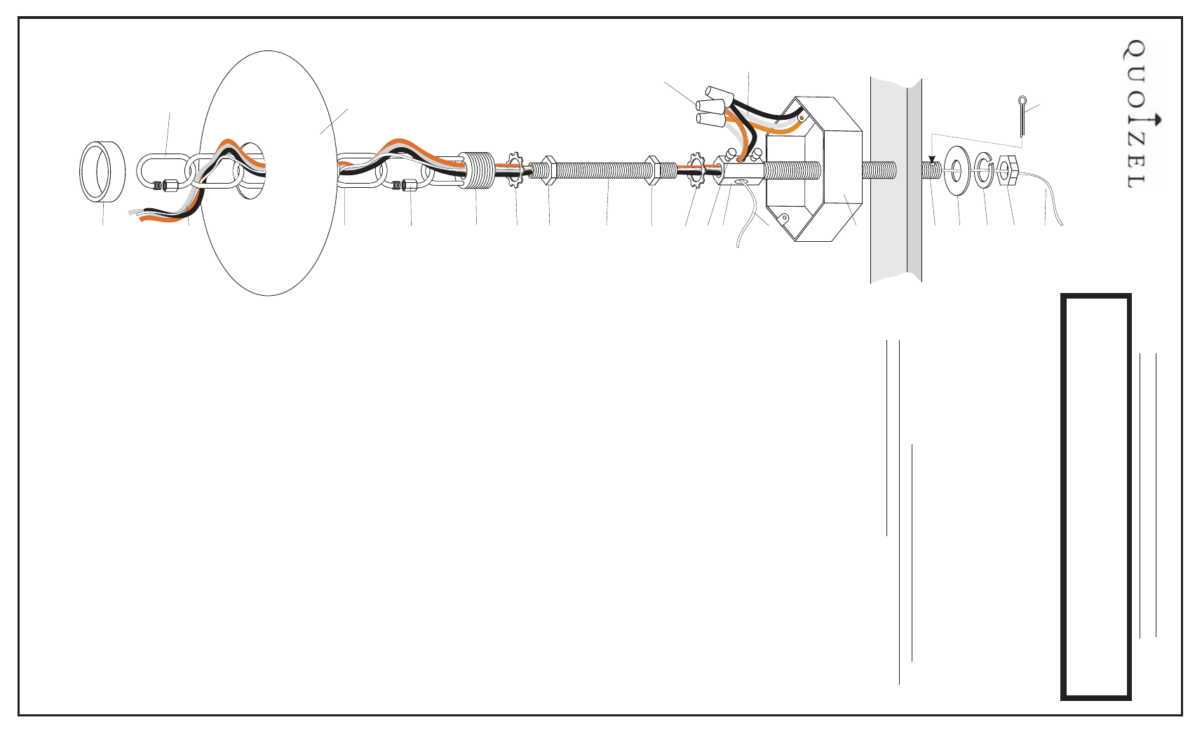
.
.
With
your
fixture
still
not
mounted
yet,
proceed
to
unravel
the
FIXTURE
WIRES,
GROUND
WIRE
and
the
SAFETY
CABLE.
Locate
the
FIXTURE
CHAIN
and
attach
one
end
of
it
to
the
FIXTURE
LOOP
at
the
top
of
the
FIXTURE
with
a
QUICK-LINK
CONNECT
OR.
Next
decide
the
length
of
chain
needed
for
your
application.
Y
o
u
will
be
required
to
remove
excess
links
with
bolt
cutters.
Proceed
to
pass
the
FIXTURE
WIRES,
GROUND
WIRES
and
SAFETY
CABLE
through
alternating
links
on
the
chain.
Proceed
to
pass
the
wires
through
the
following
mounting
components
in
this
order
and
how
it
is
shown
in
the
illustration
on
the
left:
1)
CANOPY
LOCK
RING;
2)
CEILING
CANOPY;
3)
CANOPY
CHAIN
LOOP;
4)
LOCK
W
ASHER
B
and
LOCKNUT
B;
5)
NIPPLE;
6)
LOCK
NUT
A
and
LOCK
W
ASHER
A
Thread
LOCK
NUTS
A
and
B
approx.
½”
onto
each
end
of
the
NIPPLE,
also
slip
on
LOCK
W
ASHERS
A
and
B.
3.
Position
the
fixture
under
the
OUTLET
BOX
and
pass
the
fixture
wires
through
the
bottom
center
of
the
COUPLING.
Pull
wires
through
the
wire
way
hole
on
one
side
of
the
COUPLING.
Assemble
the
threaded
NIPPLE
into
the
bottom
of
the
HEX
COUPLING
until
it
is
visible
in
the
side
hole
opening.
Thread
LOCK
NUT
A
and
LOCK
W
ASHER
A
u
p
the
NIPPLE
until
they
are
against
the
bottom
of
the
HEX
COUPLING
and
tighten
with
pliers
or
a
wrench.
4.
Next
6.
Push
the
CEILING
CANOPY
up
over
the
OUTLET
BOX.
Be
sure
that
all
wires
are
carefully
tucked
into
the
OUTLET
BOX
cavity
.
Secure
against
ceiling
by
threading
CANOPY
LOCK
RING
onto
the
CANOPY
LOOP
.
T
ighten
until
snug.
ST
OP
HERE!
For
SAFETY
CABLE
ROUTING,
go
to
page
3
and
choose
either
OPTION
A
o
r
OPTION
B.
If
you
choose
OPTION
B,
the
cable
must
exit
the
HEX
COUPLING
from
the
opposite
side
hole
of
the
wiring.
Once
that
is
determined
and
applied,
return
back
to
the
steps
below
.
NOTE:
DO
NOT
THREAD
NIPPLE
BEYOND
SIDE
HOLE
OPENING,
DAMAGE
T
O
WIRING
AND
POSSIBLE
ELECTRICAL
SHOCK
COULD
OCCUR!
1
e
2
thread
the
CANOPY
CHAIN
LOOP
into
the
bottom
of
the
NIPPLE.
T
ighten
down
HEX
NUT
B
and
LOCK
W
ASHER
B
against
it
with
pliers
or
a
wrench.
Raise
the
fixture
and
attach
the
FIXTURE
CHAIN
to
the
CANOPY
CHAIN
LOOP
with
a
QUICK-LINK
CONNECT
OR.
Pull
up
all
the
slack
in
the
wire
and
the
safety
cable.
Y
o
u
can
now
trim
the
wires
down
to
no
less
than
6”
and
begin
splicing
them
together
.
Using
wire
connectors
(not
provided)
connect
the
HOUSE
GROUND
WIRE
to
the
FIXTURE
GROUND
WIRE:
connect
the
HOUSE
WHITE
WIRE
to
the
FIXTURE
SUPPL
Y
WIRE
(white
or
ribbed
side):
connect
the
HOUSE
BLACK
(or
red)
WIRE
to
the
FIXTURE
SUPPL
Y
WIRE
(black
or
smooth
side).
W
rap
each
connection
with
approved
electrical
tape.
5.
the
the
CEILING
CANOPY
the
the
7.
Refer
back
to
Page
1,
Step
7
and
finish
installation.
The
weight
of
this
fixture
will
require
a
means
of
support
INDEPENDENT
of
the
OUTLET
BOX.
This
fixture
must
b
supported
by
a
3/8-18
NPSM
PIPE
(supplied).
Assemble
the
3/8-18
NPSM
PIPE
to
the
HEX
COUPLING
until
it
is
visible
in
the
side
hole
opening.
(Note
that
the
PIPE
has
a
cotter
pin
hole
on
one
end,
do
not
thread
that
end
into
the
HEX
COUPLING).
T
ighten
the
SET
SCREW
which
will
lock
the
pipe
in
place.
Note:
the
opposite
end
of
the
PIPE
must
be
attached
to
a
structural
or
bridging
member
of
sufficient
strength
to
support
the
fixture
weight.
A
5/8”
diameter
clearance
hole
must
be
drilled
on
the
top
inside
center
of
the
OUTLET
BOX
AND
THROUGH
THE
STRUCTURAL
SUPPORT
MEMBER.
Slip
the
PIPE
up
through
the
clearance
hole
in
the
outlet
box
and
the
structural
member
.
Install
the
LARGE
FLA
T
W
ASHER,
LOCK
W
ASHER
AND
LARGE
HEXNUT
onto
the
top
side
of
the
PIPE
and
hand
tighten
until
the
coupling
touches
the
top
inside
of
the
outlet
box.
Now
install
the
cotter
pin.
NOTE:
DO
NOT
CUT
THE
SAFETY
CABLE
A
T
THIS
TIME!
ST
OP
HERE!
Before
securing
the
CEILING
CANOPY
to
the
ceiling,
refer
to
Page
3
for
the
SAFETY
CABLE
/
TUCK
W
ASHER
INST
ALLA
TION
STEPS.
Once
that
assembly
is
completed
and
the
cable
is
secured,
you
can
refer
back
to
Step
#6
below
to
complete
your
fixture
installation.
NOTE:
IT
IS
RECOMMENDED
THA
T
THE
STRUCTURAL
OR
BRIDGING
MEMBER
SUPPORT
4
TIMES
THE
ACTUAL
WEIGHT
OF
THE
FIXTURE.
.
6
C
ORPORA
TE
P
A
RKW
A
Y
GOOSE
CREEK
SC
29445
www
quoizel
com
,.
..
CEILING
INST
A
LLA
TION
INSTRUCTIONS
FOR
FIXTURES
W
EIGHING
O
VER
45
LBS.
NOTE:
DUE
T
O
THE
HANGING
W
EIGHT
O
F
T
HIS
FIXTURE,
Q
UOIZEL
HIGHL
Y
RECOMMENDS
YOU
C
ONSUL
T
A
LICENSED
ELECTRICIAN
OR
QUALIFIED
C
ONTRACT
OR
FOR
THIS
INST
ALLA
TION.
QUOIZEL
R
ECOMMENDS
(2)
PEOPLE
FOR
THIS
INST
ALLA
TION
COTTER
P
IN
HOUSE
S
UPPL
Y
and
GROUND
WIRES
OUTLET
BOX
(NOT
SUPPLIED)
SET
SCREWS
HEX
C
OUPLING
LOCK
W
ASHER
A
LOCK
W
ASHER
B
LOCK
NUT
A
LOCK
NUT
B
CANOPY
CHAIN
LOOP
HEXNUT
SAFETY
C
ABLE
OPTION
“A”
SAFETY
C
ABLE
OPTION
“B”
NIPPLE
QUICK-LINK
CONNECT
OR
QUICK
L
INK
CONNECT
OR
CANOPY
FIXTURE
CHAIN
FIXTURE
SUPPL
Y
WIRES
&
SAFETY
CABLE
STRUCTURAL
O
R
BRIDGING
MEMBER
CANOPY
LOCK
RING
WIRE
C
ONNECT
ORS
(NOT
SUPPLIED)
3/8-18
NPSM
PIPE
FLA
T
W
ASHER
LOCK
W
ASHER
IS-TF1784
P
a
g
e2o
f3
Revised
2007-12-19