Quoizel PTD2826BN Portland User Manual
Page 4
Thank you for purchasing a Quoizel product.
Need assistance with parts or assembly? Call Quoizel customer service at 1-631-273-2700
or visit us on-line at www.quoizel.com
4of5
6 CORPORATE PARKWAY
GOOSE CREEK SC 29445
www quoizel com
,
.
.
.
2014 QuoizelInc.
Assembly Instruction Sheet #IS-PTD2826BN
For Style PTD2826BN
May2014
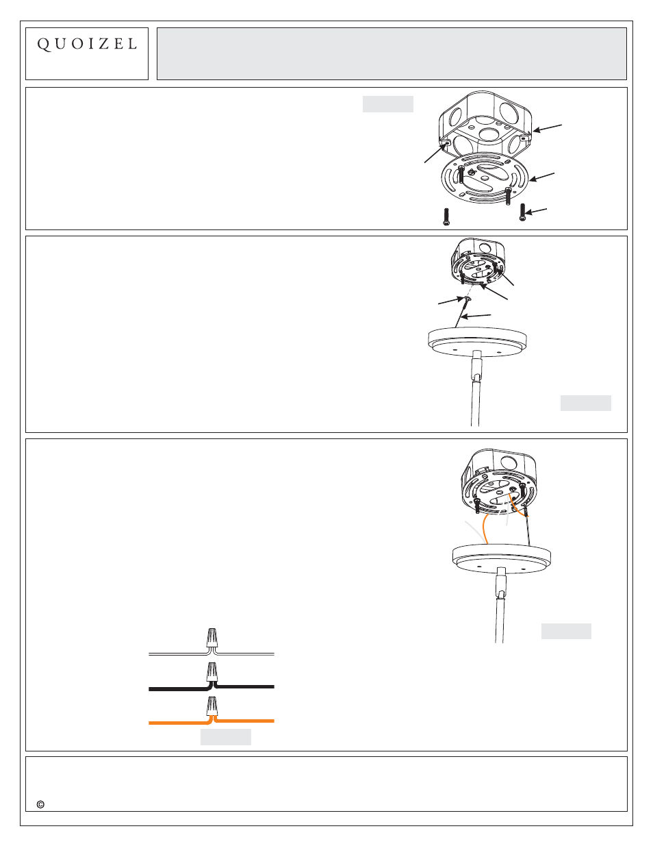
Figure 5
STEP 5
- Attach Lanyard
A. The purpose of the lanyard is to provide the installer a
means to support the fixture from the junction box while
connecting the electrical wires. This enables the fixture
to hang from the junction box and your hands are free to
make the wire connections.
B. Turn the Button Stop so it is inserted into the crossbar
slot. Make sure the Button Stop is completely inside the
crossbar. Slowly release the fixture to make sure it is
supported by the Button Stop. Proceed to the wiring
steps. Once you are complete with the wiring there is
nothing to do with Lanyard. The Lanyard will push into
the junction box when the fixture is placed for final
mounting.
Crossbar
Button Stop
Lanyard
Slot
STEP 4
- Attach Crossbar to Outlet Box
A. Attach the Crossbar (A) to Outlet Box and secure by
threading Outlet Box Screws (not supplied) into the
Mounting Holes on the Outlet Box. Tighten until snug.
Figure 4
Crossbar
Outlet
Box
Outlet Box
Screw
Mounting
Hole
Figure 6
STEP 6
Make Wire Connections
-
A. Use standard wire connectors to make all wire
connections. (Connectors are not included with fixture.)
Strip and prepare wire ends according to instructions
supplied with connectors.
B. Connect White Supply Wire from the Outlet Box to White
Wire from fixture.
C. Connect Black (or Red) Supply Wire from the Outlet Box
to Black Wire from fixture.
D. Connect Ground Wire from the Outlet Box to Ground
Wire from fixture.
E. Twist connectors until wires are tightly joined together.
F. Wrap each connection with approved electrical tape and
carefully stuff all the connected wires into the Outlet Box.
Figure 7
White wire from supply
White wire from fixture
Black wire from supply
(or Red)
Black wire from fixture
Ground wire from supply
Ground wire from fixture