Quoizel MY5005ML Monterey Mosaic User Manual
Assembly / installation instructions
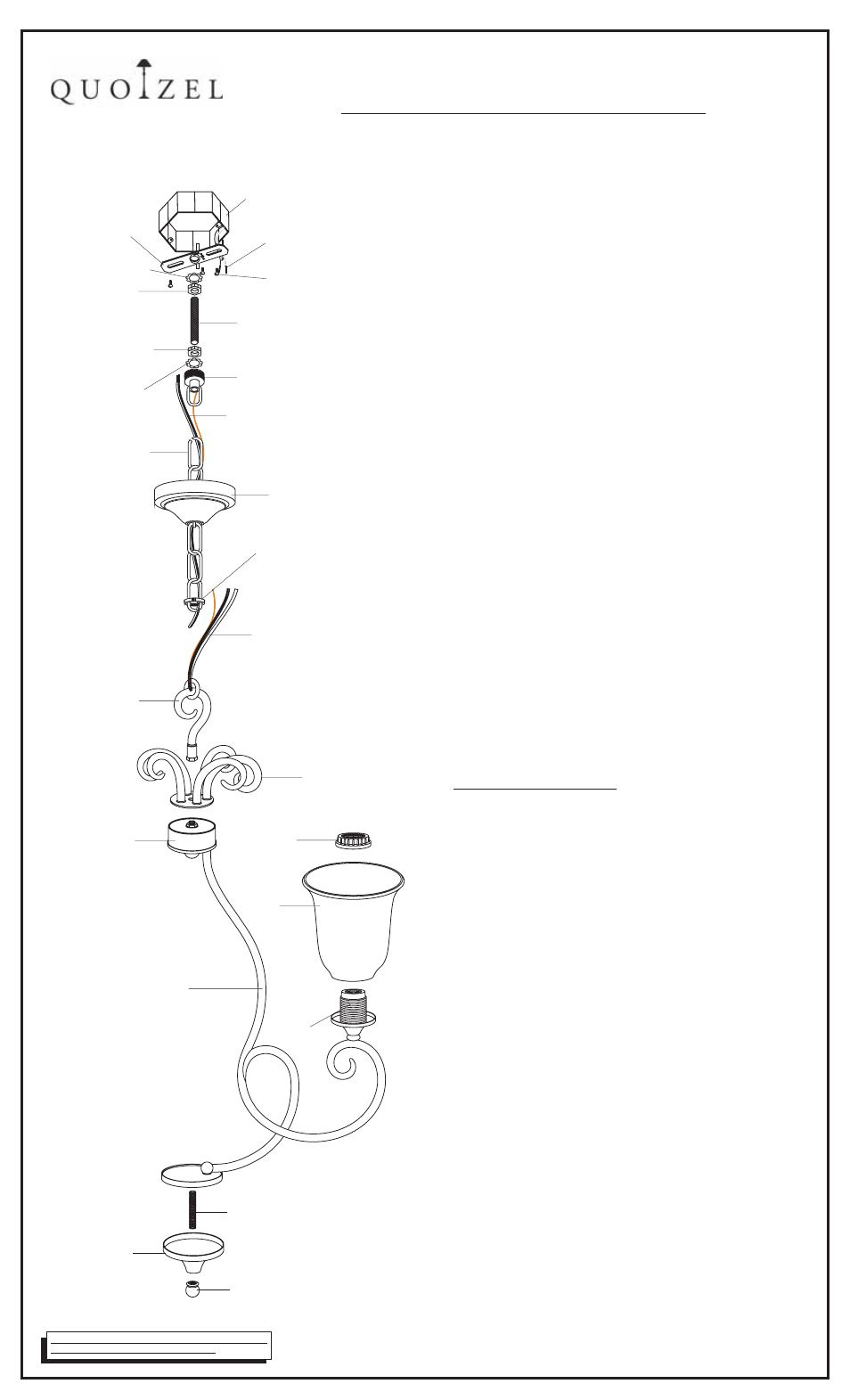
OUTLET BOX
HOUSE SUPPLY and
GROUND WIRES
OUTLET BOX SCREWS
not supplied
(
)
CROSSBAR
LOCK WASHER A
LOCK NUT A
NIPPLE
LOCK NUT B
LOCK WASHER B
CANOPY CHAIN LOOP
FIXTURE SUPPLY
and GROUND WIRE
FIXTURE CHAIN
CEILING CANOPY
CANOPY LOCK RING
FIXTURE SUPPLY
and GROUND WIRE
FIXTURE LOOP
SCROLL PART
SOCKET
COLLAR
JUNCTION BOX
SHADE
SOCKET
SUPPORT ARM
1 Before beginning the installation carefully unpack and
identify all parts referring to the illustration
2 Turn power to the installation point OFF at circuit breaker
3 Unfold the SUPPORTARMS to the proper locations.
Locate the SCROLL PART onto the top end of the
JUNCTION BOX and make the hole on the bottom of it
over the nipple on the top center of the JUNCTION BOX.
Thread the FIXTURE LOOP onto the nipple and hand
tighten until snug to secure them.
4 Thread the NIPPLE into the hex coupling on the bottom
center of the SUPPORT ARMS assembly Hand tighten
until snug Proceed to locate the FIXTURE COVER
over the end of the NIPPLE and secure with the FINIAL
Hand tighten until snug
5. Fasten the CROSSBAR to the OUTLET BOX with
(2)OUTLET BOX SCREWS(not supplied). Proceed to
thread LOCK NUT A and LOCK WASHER A onto
the top end of NIPPLE. Thread NIPPLE into the center of
CROSSBAR. Locate the LOCK NUT B onto the bottom end
of the NIPPLE. Tighten LOCK NUT A against CROSSBAR
with plier until snug.
6. Locate the FIXTURE CHAIN and determine desired
hanging height of fixture. Adjust chain by removing links if
needed. Please note that depending on chain material
thickness, you might be required to use chain pliers to
spread links open. Proceed to attach one end of chain to
FIXTURE LOOP, attached to top of fixture. Pass the
fixture wires through FIXTURE CHAIN alternating links.
Proceed to pass the fixture wires through the following
mounting components in this order: 1)CANOPY LOCK
RING; 2)CEILING CANOPY 3 CANOPY CHAIN LOOP
4 LOCK WASHER B and LOCK NUT B 5 NIPPLE
6 LOCK NUT A and LOCK WASHER A
7.
(2 people recommended for the remaining steps) Position
the fixture under the ceiling mounted outlet box. Pass
LOCK WASHER B over the NIPPLE. Thread CANOPY
CHAIN LOOP onto NIPPLE. Thread LOCK NUT B down
the NIPPLE, against the CANOPY CHAIN LOOP and snug
with pliers. Pass the wires through the NIPPLE. Take up
wire slack and trim wires so that approx. 6” will remain
inside outlet box. Proceed to attach the top of the FIXTURE
CHAIN to the bottom of the CANOPY CHAIN LOOP.
Using wire connectors (not supplied) connect the
HOUSE GROUND WIRE to the FIXTURE GROUND
WIRE connect the HOUSE WHITE WIRE to the
FIXTURE SUPPLY WIRE (WHITE or RIBBED SIDE);
connect the HOUSE BLACK (or RED) WIRE to the
FIXTURE SUPPLY WIRE(BLACK or SMOOTH SIDE).
Wrap each connection with approved electrical tape.
8. With the proper connections made, proceed to push the
CEILING CANOPY upward over the OUTLET BOX. Be
sure that all wires are carefully tucked into the OUTLET
BOX cavity. Secure canopy against ceiling by threading
CANOPY LOCK RING onto the CANOPY LOOP. Tighten
until snug.
9. Position the SHADE over the SOCKET as shown. Secure
the SHADE by threading the SOCKET COLLAR onto the
SOCKET. Hand tighten until snug.
10.Install the correct bulbs referring to fixture marking and/or
labels for maximum wattage.
11 Restore power to the installation point ON. Retain this
sheet for future reference.
.
.
.
,
,
.
.
.
.
.
.
.
; )
;
)
; )
;
)
.
;
.
Making the connections:
ASSEMBLY / INSTALLATION INSTRUCTIONS
IF IN DOUBT ABOUT ELECTRICAL INSTALLATION,
CONSULT A LICENSED ELECTRICIAN!
IS-MY5005
2007-10 16
-
6 CORPORATE PARKWAY
GOOSE CREEK SC 29445
www quoizel com
,
.
.
.
NIPPLE
FIXTURE COVER
FINIAL