Quoizel TFMT2824IB Marietta User Manual
Page 2
2of3
Thank you for purchasing a Quoizel product.
Need assistance with parts or assembly? Call Quoizel customer service at 1-631-273-2700
or visit us on-line at
2014 QuoizelInc.
January2014
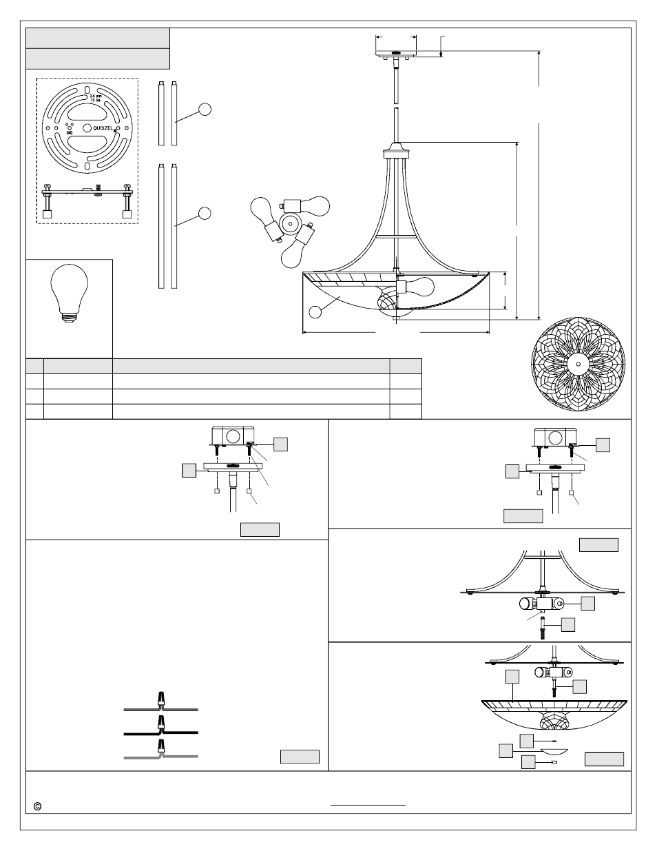
TFMT2824IB
PART NUMBER
NOTE: ALL DIMENSIONS ARE ROUNDED UP TO THE NEAREST 1/2"
REPLACEMENT PART DESCRIPTION
REQ.
NO.
(3) 100W
Bulbs
(Not Supplied)
Medium
Base
1
FINISH: IMPERIAL BRONZE
Mounting Screw
Hex Nut and
Lock Washer
A
AA
Mounting Ball
Figure 3
of the nipple on the Crossbar
Assembly (AA) by unscrewing
the preassembled hex nut and
lock washer and then screwing
the mounting screws in or out of
the crossbar until the correct
length is achieved. Once the
Ceiling Canopy (A) is secure,
remove the mounting ball and
Ceiling Canopy (A) and proceed
to Step 4.
STEP 4
Wire Connections
-
A. Use standard wire connectors (not included) to make all wire
connections. (Connectors are not included with fixture.) Strip and
prepare wire ends according to instructions supplied with
connectors.
B. Connect White Supply Wire from the Outlet Box to Ribbed Side Wire
from fixture.
C. Connect Black (or Red) Supply Wire from the Outlet Box to Smooth
Side Wire from Fixture.
D. Connect Ground Wire from the Outlet Box to Ground Wire from
fixture.
E. Twist connectors until wires are tightly joined together.
F. Wrap each connection with approved electrical tape and carefully
stuff all the connected wires into the Outlet Box.
White wire
from supply
Black wire from
supply (or Red)
Ground wire
from supply
Ribbed side wire
from fixture
Smooth side wire
from fixture
Ground wire
from fixture
Figure 4
Mounting
Screw
A
AA
Mounting Ball
Figure 5
STEP 5
Install Fixture Body
-
A. Carefully tuck all wires into the outlet
box and position the Ceiling Canopy
(A) over the outlet box. Align the
holes in the Ceiling Canopy (A) with
the mounting screws, then attach the
Ceiling Canopy (A) using the
previously removed mounting balls.
Hand tighten until snug.
STEP 6
Install Stem with Hex Nut
-
A. Thread the beaded end of the Stem
(D) into the Coupling underside of the
Socket Assembly (F). Hand tighten
until snug.
D
F
Figure 6
Coupling
STEP 7
Install Shade
-
A. Adjust the Hex Nut on the Stem
(D) to proper location for the rest
components. Place the Shade
(G) over the end of the Stem (D)
and secure with the Hex Nut (E).
Hand tighten until snug.
B. Place the Cap (H) over the end
of the Stem (D) and secure with
the Finial (I). Hand tighten until
snug.
G
E
Figure 7
I
H
D
23.5
” Dia.
4.5
”
22.5
”
60.5
”
OVERALL HEIGHT
(2) 6
” AND (2) 12” RODS
INCLUDED
5
” Dia.
0.5
”
NOTE: ONE LIGHT SHOWN FOR
ILLUSTRATION PURPOSES ONLY.
2
3
3
2
1
2
9012EXIB
9006EXIB
G3599SH
ROD EXTENSION IMPERIAL BRONZE 12"L X 0.5"D
ROD EXTENSION IMPERIAL BRONZE 6
”L X 0.5"D
JADE SHADE 24"D
2
1