Quoizel TFKM2840VB Kami User Manual
Page 2
2of3
Thank you for purchasing a Quoizel product.
Need assistance with parts or assembly? Call Quoizel customer service at 1-631-273-2700
or visit us on-line at
2014 QuoizelInc.
May2014
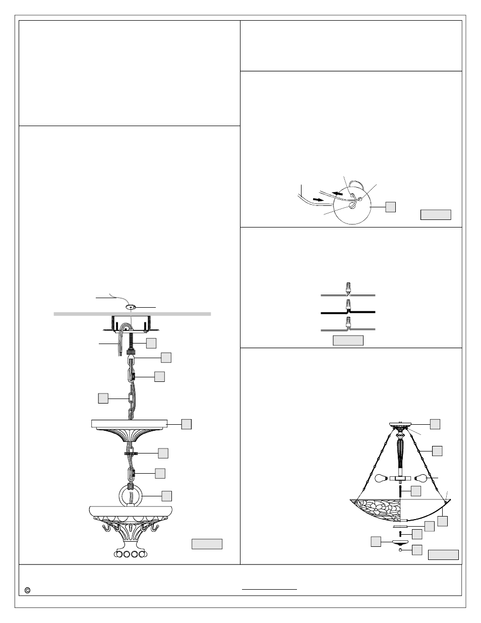
STEP 3 - Install Fixture Chain, Safety Cable and Ceiling Canopy
A. Adjust Fixture Chain (GG) to your desired length by removing the
links if needed.
Pliers is required for this step.
B. With Fixture Chain (GG) not attached to Fixture Loop (A) and
Canopy Chain Loop (EE), pull supply wires and safety cable
through Fixture Chain (GG) alternating links. After wires and safety
cable are through Fixture Chain (GG), pull Supply Wires, Ground
Wire and safety cable through Canopy Lock Ring (FF) and Ceiling
Canopy (II) in order.
C. Attach one end of Fixture Chain (GG) to Fixture Loop (A) with one
Quick Link (HH). Lift fixture and Fixture Chain (GG) up and attach
other end of Fixture Chain (GG) onto Canopy Chain Loop (EE) with
another Quick Link (HH). The fixture will now hang safely. Close
chain loop at Ceiling Canopy Loop (EE).
D. Feed Supply Wires, Ground Wire and Safety Cable through
Canopy Chain Loop (EE) and Nipple (DD) into Outlet Box. Cut wires
leaving approximately 8
” of wire extending from the Outlet Box.
E. Refer to Step 4 for safety cable installation.
F. Refer to Step 5 for wire connections.
G. Raise Ceiling Canopy (II) and Canopy Lock Ring (FF) up Fixture
*
DD
A
GG
II
Supply Wires
and Ground Wire
Chain (GG) and over Canopy Chain Loop (EE). Tighten Canopy
Lock Ring (FF) onto Canopy Chain Loop (EE) until tight.
Suggested chain length for Ceiling height :
9
’ ceiling : use 7 links of chain and 2 quick links
10
’ ceiling : use 16 links of chain and 2 quick links
EE
FF
HH
HH
12
1
Safety
Cable
12 O clock Hole
'
1 O clock Hole
'
Center Hole
C. Thread another Hex Nut (CC) to the middle of the Nipple (DD). Place
another Lock Washer (BB) over the Nipple (DD) and then thread the
Nipple (DD) into the Crossbar (AA) until the Nipple (DD) is about
0.375
” above the Crossbar (AA).
D. Remove the Canopy Lock Ring (FF) from the Canopy Chain Loop
(EE). Place the Ceiling Canopy (II) over the Canopy Chain Loop
(EE) against the ceiling to determine the correct position of the
Nipple (DD). Thread the Canopy Lock Ring (FF) onto the Canopy
Chain Loop (EE). Adjust the Nipple (DD) to allow the Ceiling Canopy
(II) to rest against the ceiling when held in place by the Canopy Lock
Ring (FF).
D. Remove the Canopy Lock Ring (FF) and the Ceiling Canopy (II).
Tighten the Hex Nut (CC) against the Crossbar (AA) to secure in
place.
Safety Cable
Tuck Washer
STEP 4 - Install Safety Cable
A. Push all slack Safety Cable through center hole of Outlet
Box
Structural or Bridging Member and Tuck Washer (JJ).
B. Push the Cable down through the 12 O
’clock Hole. Leaving ½”of
slack. Then push the Cable up through the 1 O
’clock Hole and tuck
it under the cable between the Center Hole and the 12 O
’clock
Hole.
C. Pull all of excess cable through all of the holes until the Tuck
Washer is very close to the Structural or Bridging Member.
Remove as much slack as possible out of the Tuck Washer. About
½”of slack between Tuck Washer and the hole is acceptable.
,
JJ
White wire
from supply
Ribbed side wire
from fixture
Black wire from
supply (or Red)
Smooth side wire
from fixture
Ground wire
from supply
Ground wire
from fixture
Figure 5
STEP 5 - Wire Connections
A. Use standard wire connectors (not included) to make all wire
connections. (Connectors are not included with fixture.) Twist
connectors until wires are tightly joined together. Wrap each
connection with approved electrical tape and carefully stuff all the
connected wires into outlet box.
Figure 3
Figure 4
B
Hook
C
D
E
F
G
H
I
Loop
Bulb
STEP 6
Install Shade, Cap and Bulb
-
Quoizel recommends (2) people for this step.
A. Thread one end of 4.73
”L Nipple with Hex Nut (D) into the hex
coupling on the bottom center of Socket Assembly (B). Hand tighten
until snug.
B. Place Shade (E) over the end of 4.73
”L Nipple with Hex Nut (D).
With one person hold the Shade (E), another person attach one
ends of Side Arms (C) to the Hooks at the side of Socket Assembly
(B) and attach another ends of
Side Arms (C) to the Loops in
Shade (E).
C. Place Inner Cap (F) onto the
end of 4.73
”L Nipple with Hex
Nut (D) and secure by threading
hex nut end of 2
”L Nipple with
Hex Nut (G) into the end of
4.73
”L Nipple (D). Place Cap
(H) onto 2
”L Nipple (G) and
secure with Finial (I). Hand
tighten until snug.
D. This fixture uses standard bulb
with standard screw base.
Maximum 100 watts. Insert bulb
and screw snugly into place.
Your fixture is now assembled
and ready to use. Enjoy!
Figure 6