Quoizel TFKM2820VB Kami User Manual
Page 2
2of3
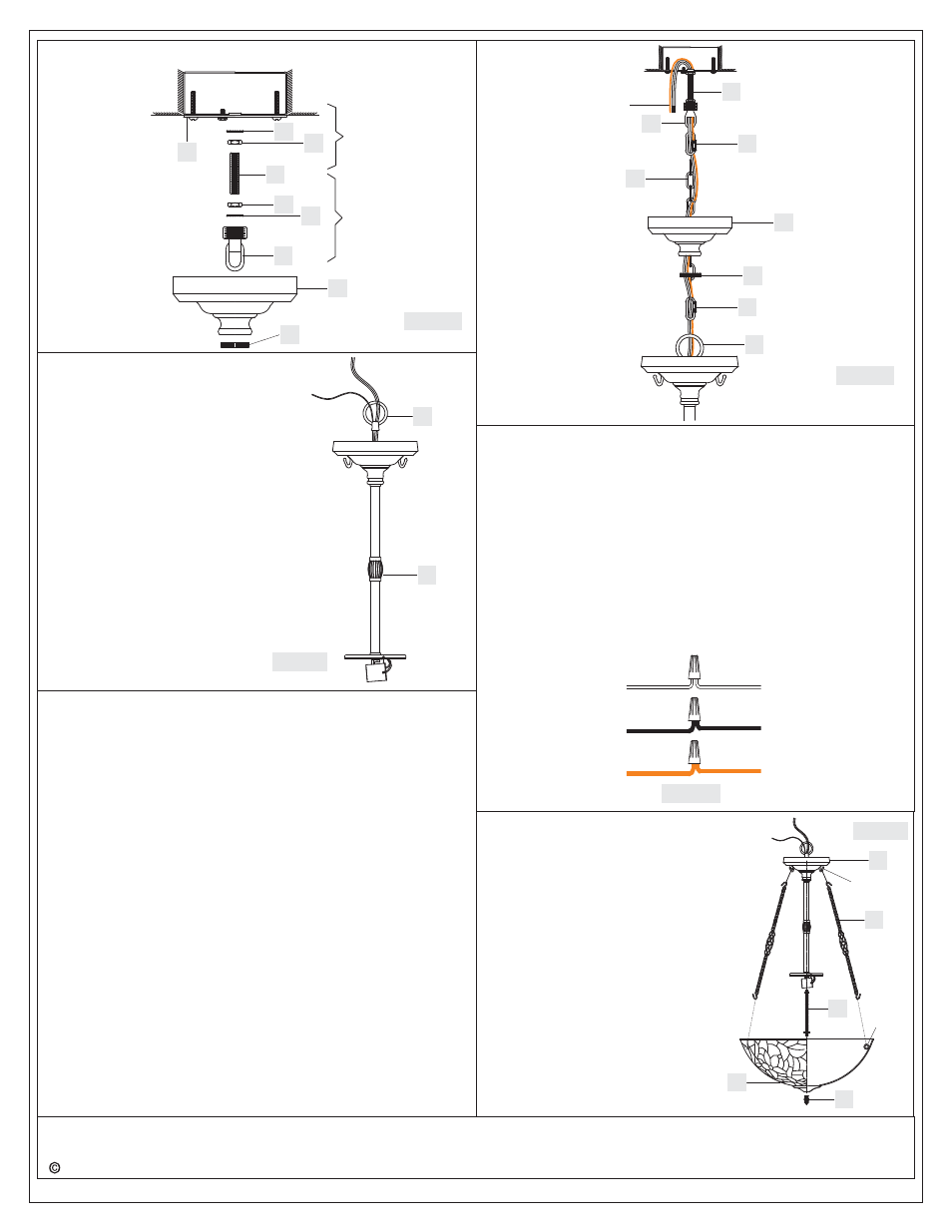
Figure 2
AA
BB
CC
DD
CC
BB
EE
FF
II
Thank you for purchasing a Quoizel product.
Need assistance with parts or assembly? Call Quoizel customer service at 1-631-273-2700
or visit us on-line at www.quoizel.com
2014 QuoizelInc.
March2014
Tighten the Hex Nut (CC) against the Crossbar (AA) to secure in
place.
STEP 4 - Install Fixture Chain and Ceiling Canopy
A. Adjust the Fixture Chain (GG) to your desired length by removing
the links if needed.
Pliers is required for this step.
B. With the Fixture Chain (GG) not attached to the Fixture Loop (A)
and the Canopy Chain Loop (EE), pull the supply wires through the
Fixture Chain (GG) alternating links. After the wires are through the
Fixture Chain (GG), pull the Supply Wires and the Ground Wire
through the Canopy Lock Ring (FF) and the Ceiling Canopy (II) in
order.
C. Attach one end of the Fixture Chain (GG) to the Fixture Loop (A)
with one Quick Link (HH). Lift the fixture and Fixture Chain (GG) up
And Attach the other end of the Fixture Chain (GG) onto the Canopy
Chain Loop (EE) with another Quick Link (HH). The fixture will now
*
hang safely. Close the chain loop at the Ceiling Canopy Loop (EE).
D. Feed the Supply Wires and Ground Wire through the Canopy Chain
Loop (EE) and Nipple (DD) into the Outlet Box. Cut the wires
leaving approximately 8” of wire extending from the Outlet Box.
E. Refer to Step 6 for wire connections.
F. Raise the Ceiling Canopy (II) and Canopy Lock Ring (FF) up the
Fixture Chain (GG) and over the Canopy Chain Loop (EE). Tighten
the Canopy Lock Ring (FF) onto the Canopy Chain Loop (EE) until
tight.
Suggested chain length for Ceiling height :
8’ ceiling : use 1 link of chain and 2 quick links
9’ ceiling : use 11 links of chain and 2 quick links
10’ ceiling : use 21 links of chain and 2 quick links
Figure 4
DD
A
GG
II
Supply Wires
and Ground Wire
STEP 5 - Wire Connections
A. Use standard wire connectors (not included) to make all wire
connections. (Connectors are not included with fixture.) Strip and
prepare wire ends according to instructions supplied with
connectors.
B. Connect White Supply Wire from the Outlet Box to Ribbed side
Wire from fixture.
C. Connect Black (or Red) Supply Wire from the Outlet Box to Smooth
side Wire from fixture.
D. Connect Ground Wire from the Outlet Box to Ground Wire from
fixture.
E. Twist connectors until wires are tightly joined together.
F. Wrap each connection with approved electrical tape and carefully
stuff all the connected wires into the Outlet Box.
White wire
from supply
Ribbed side wire
from fixture
Black wire from
supply (or Red)
Smooth side wire
from fixture
Ground wire
from supply
Ground wire
from fixture
Figure 5
Step A
Step B
EE
FF
HH
HH
STEP 3
Install Fixture Loop
-
A. Thread the Fixture Loop (A) onto the
nipple on the top center of the Socket
Assembly (B). Hand tighten until snug.
Figure 3
A
B
STEP 6
Install Shade
-
Quoizel recommends (2) people for this step.
A. Thread the short nipple end of the Center
Stem (D) into the hex coupling on the bottom
center of the Socket Assembly (B). Hand
tighten until snug.
B. Place the Shade (F) over the end of the
Center Stem (D). With one person hold the
F
C
D
E
B
Hook
Loop
Shade (F), another person attach one
end of the Side Arm (C) to the Hook at
the Socket Assembly (B) and attach
another ends of the Side Arms (C) to
the Loops in the Shade (F).
C. Thread the Finial (E) onto the end of
the Center Stem (D). Hand tighten
until snug.
Figure 6