Quoizel BWL2822CC Brown Lattice User Manual
Page 2
2of2
Thank you for purchasing a Quoizel product.
Need assistance with parts or assembly? Call Quoizel customer service at 1-631-273-2700
or visit us on-line at www.quoizel.com
2014 QuoizelInc.
February2014
White wire
from supply
Ribbed side wire
from fixture
Black wire from
supply (or Red)
Smooth side wire
from fixture
Ground wire
from supply
Ground wire
from fixture
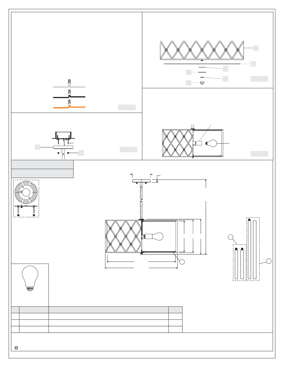
Figure 4
STEP 7
Install Bulb
-
A. This fixture uses standard bulb with medium screw base. Maximum
100 watts.
B. Insert bulb and screw snugly into place.
Your fixture is now assembled and ready to use.
Enjoy!
Socket
Bulb
Figure 7
BWL2822CC
PART NUMBER
NOTE: ALL DIMENSIONS ARE ROUNDED UP TO THE NEAREST 1/2
"
REPLACEMENT PART DESCRIPTION
REQ.
2
2
1
NO.
(4) 100W
Bulbs
(Not Supplied)
Medium
Base
1
2
3
FINISH: COPPER CANYON
STEP 6
Attach Shade to fixture
-
A. Place the Diffuser (G) , Rubber Washer (H) and Flat Washer (I)over
the Center Stem, secure with the Hex Nut (J). Hand tighten until
sung.
B. Thread the Finial (K) onto the Center Stem, hand tighten until sung.
5.5” Dia.
1”
49”
OVERALL HEIGHT INCLUDES
(2) 6” AND (2) 12” RODS
22” Dia.
11”
GND
STEP 4 - Wire Connections
A. Use standard wire connectors (not included) to make all wire
connections. (Connectors are not included with fixture.) Strip and
prepare wire ends according to instructions supplied with
connectors.
B. Connect White Supply Wire from the Outlet Box to Ribbed side
Wire from fixture.
C. Connect Black (or Red) Supply Wire from the Outlet Box to Smooth
side Wire from fixture.
D. Connect Ground Wire from the Outlet Box to Ground Wire from
fixture.
E. Twist connectors until wires are tightly joined together.
F. Wrap each connection with approved electrical tape and carefully
stuff all the connected wires into the Outlet Box.
STEP 5
Attach Fixture Body to Mounting Screw
-
A. Place the Backplate of the Fixture Body (A) over the Mounting
Screws and secure with Lock Ball (B). Hand tighten until snug.
Figure 5
A
B
Mounting Screw
F
G
H
I
J
K
10”
9.5”
21” Dia.
Figure 6
9008EXCC
9007EXCC
G147DI
ROD
COPPER CANYON 12"L X .63"D
EXTENSION
ROD
COPPER CANYON 6"L X .63"D
EXTENSION
DIFFUSER FROSTED GLASS 20.25"D
1
2
3