Measur ement antennas, 3/high frequency dipole family, 2/medium frequency dipole family – ORBIT FR Electric sleeve dipoles User Manual
Page 3: Mechanical characteristics
17
>
Measur
ement antennas
Mechanical characteristics
Part number
Frequency range
A mm
B mm
C mm
D mm
Connector Type
Weight
SD 1230
1165 – 1295 MHz
178.7
123.2
9.8
15
PC 3.5 Female
1
75
g
(approx)
SD 1450
1390 – 1540 MHz
156.1
109.0
9.8
15
PC 3.5 Female
1
75
g
(approx)
SD 1575
1500 – 1630 MHz
148.6
105.2
9.8
15
PC 3.5 Female
1
75
g
(approx)
SD 1730
1640 – 1830 MHz
132.7
93.2
9.8
15
PC 3.5 Female
1
75
g
(approx)
SD 1800
1710 – 1930 MHz
131.4
93.2
9.8
15
PC 3.5 Female
1
75
g
(approx)
SD 1900
1810 – 2030 MHz
129.7
93.2
9.8
15
PC 3.5 Female
1
75
g
(approx)
SD 2050
1910 – 2170 MHz
127.9
93.2
9.8
15
PC 3.5 Female
1
75
g
(approx)
SD 2140
1990 – 2330 MHz
126.7
93.2
9.8
15
PC 3.5 Female
1
75
g
(approx)
SD 2450
2330 – 2650 MHz
122.3
93.2
9.8
15
PC 3.5 Female
1
75
g
(approx)
SD 2600
2380 – 2950 MHz
121.4
93.2
9.8
15
PC 3.5 Female
1
60
g
(approx)
(1) Huber+Suhner type 31 PC35-50-0-1/199UE
Mechanical characteristics
Part number
Frequency range
A mm
B mm
C mm
D mm
Connector Type
Weight
SD 3150-A
3000 – 3300 MHz
175.8
156
8.2
14
PC 3.5 Female
1
90
g
(approx)
SD 3600-A
3450 – 3800 MHz
172.1
156
8.2
14
PC 3.5 Female
1
90
g
(approx)
SD 4000-A
3800 – 4200 MHz
171.6
156
8.2
14
PC 3.5 Female
1
90
g
(approx)
SD 5150-A
4900 – 5400 MHz
170.1
156
8.2
14
PC 3.5 Female
1
90
g
(approx)
SD 5650-A
5400 – 5900 MHz
168.2
156
8.2
14
PC 3.5 Female
1
90
g
(approx)
(1) Type 23 PC35-50-0-51/199 UE
3/High frequency dipole family
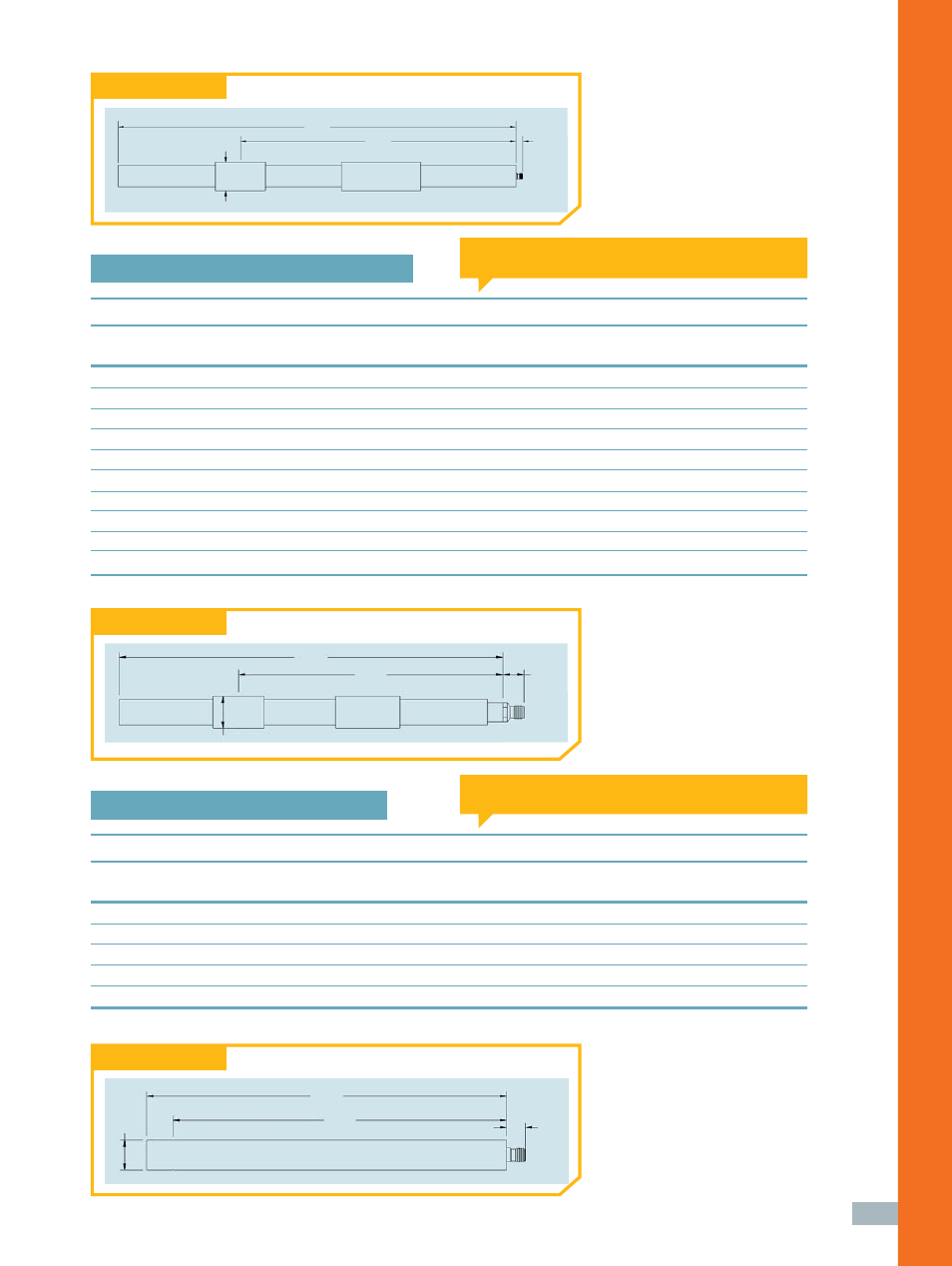
Mechanical drawing
Mechanical drawing
Mechanical drawing
“A”
“B”
“C”
“D”
“A”
“B”
“C”
“D”
“A”
“B”
“C”
“D”
“A” = Total length
“C” = Connector length
“B” = Phase center position
“D” = Diameter
“A” = Total length
“C” = Connector length
“B” = Phase center position
“D” = Diameter
2/Medium frequency dipole family