ORBIT FR AZ, EL, AZ Positioners: Light Duty User Manual
Page 2
70
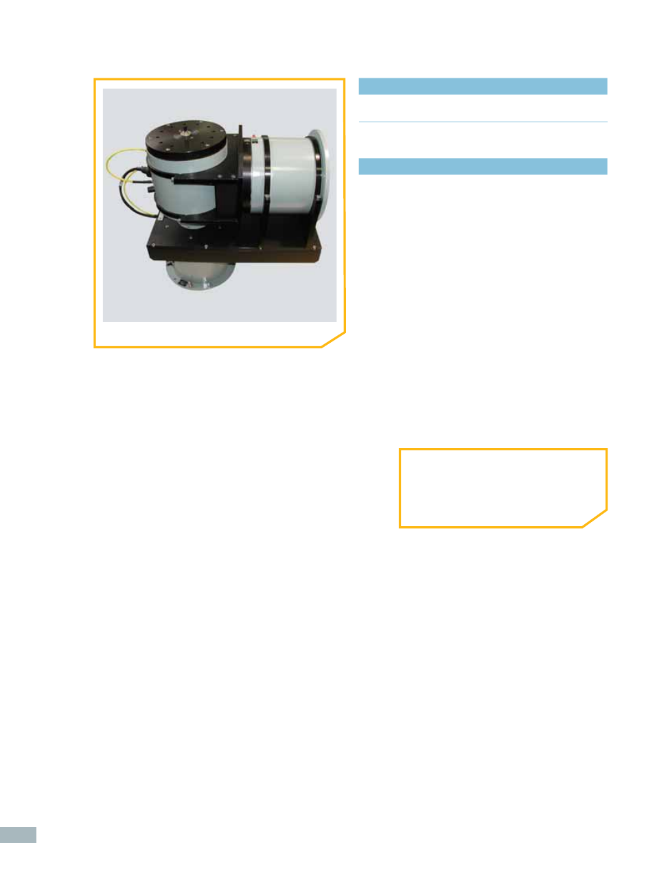
supplied accessories
>
CD-ROM Documentation Set:
User Manual (Installation, Setup, Operation & Maintenance)
technical notes
ORDERING INFORMATION
•
Refer to Legacy Series AZ/EL/AZ
Positioners – Light Duty Specifi cation
Table
1
All accuracy data is based on no-load conditions.
Contact ORBIT/FR for accuracy under load conditions.
2
Equipped with adjustable limit switches capable of
approx 20° to 900° total travel. When rotary joint and slip
ring options are specifi ed, limit switches remain but are
electrically disabled.
Multi-axis positioners are factory-set at:
•
Upper Azimuth Axis: 400° (± 200°)
•
Elevation Axis: 190° (± 95°)
•
Lower Azimuth Axis: 400° (± 200°)
3
Slip Ring & Rotary Joint Option Notes:
•
Certain slip ring options may require an extension
cap that protrudes above the turntable surface.
Positioner height may increase. Consult ORBIT/FR.
•
Slip ring contacts for customer use are provided
with dedicated connectors.
•
When rotary joint and/or slip ring options are
specifi ed, no central thru-hole is available to
the user. Option TH002 is available in lieu of rotary
joint and/or slip ring options.
❚
AL- 4568-1 Top View