Figure 2 - xgb heater dimensions – CCI Thermal Technologies XGB - Explosion-Proof Forced Air Unit Heater User Manual
Page 2
Edmonton Head Office & Factory
5918 Roper Road, Edmonton, Alberta, Canada T6B 3E1
P 780.466.3178 F 780.468.5904 Toll Free 1.800.661.8529
Part No. 11110 - Rev. 01
[email protected] www.ccithermal.com
Installation, Operation & Maintenance Instructions for
Norseman
TM
XGB Explosion-Proof Unit Heater
3.75 - 35kW, 60 Hz Units
1.0 GENERAL INFORMATION
DESCRIPTION
CCI Thermal’s
XGB explosion-proof unit heater is the latest addition
to the
NORSEMAN™ line of hazardous location heating products.
The small cabinet units are available with ratings from 3.75 – 10kW,
and can be identified by their internally mounted motor. The large
cabinet units (shown below) are available from 10kW up to 35kW.
See section 3.1 for cabinet dimensions.
APPLICATION
Designed specifically for heating industrial spaces where potentially
explosive substances are or may be present. Typical hazardous
location environments include:
• Water and Sewage Treatment Plants
• Oil Refineries
• Compressor Stations
• Pulp and Paper Mills
• Paint Storage Booths
• Cement Plants
• Mines
CONSTUCTION AND INSTALLATION
CCI Thermal’s
NORSEMAN™ unit heaters use extra heavy wall
finned tubular steel heating elements to provide safe, efficient heat
transfer to the environment.
The heater does not contain glycol,
decreasing maintenance costs.
Flow adjustment… in structures with high ceilings, other units may
not have the range of motion needed to direct air flow to the floor.
The glycol-free design of the
XGB allows the unit to be tilted to a 30º
angle below the horizontal, with an additional 35º of airflow
redirection provided by the outlet louver. For lateral airflow, the entire
louver assembly can be rotated 90º.
No conduit seal required… a factory installed conduit seal
provides the necessary isolation between the supply and control
housings. In Division 2, Zone 1 and Zone 2 applications, a field
installed conduit seal may not be required.
Simplified wiring… to facilitate installation, the NORSEMAN™
explosion-proof unit heaters feature the patented x-Max® housing
with slide out terminal block trolley for connection of the electrical
supply.
STANDARD PRODUCT FEATURES
• CSA C/US Certified for hazardous locations. Small cabinet units
approved for Class I, Div 1 & 2, Group D; Class II, Div. 1 & 2,
Groups E, F and G. Large cabinet units approved for Class I, Div. 1
& 2, Groups C & D; Class II, Div. 1 & 2, Groups E, F & G.
Note: Class II and some atmospheric groups are not available in
every kW rating.
• Optional Zone marking available.
• Ratings from 3.75 – 35kW.
• 208 – 600V, 1 or 3 phase
• Low watt density extra heavy wall tubular steel finned heating
elements with nickel plated finish
• Glycol-free design allows the heater to be tilted 30º downward
• Rotatable outlet louvers provide 35º of additional airflow redirection
• Patented x-Max® housing with track and trolley system simplifies
installation and servicing
• Heavy duty 16 ga. Stainless steel casing
• Terminals for remote thermostat connection
• Dual automatic reset high limits
• Contactor derated for extended service life
• Isolated supply connection housing eliminates the need for conduit
seals
OPTIONAL FEATURES
• Built-in, externally adjustable thermostat
• Built-in disconnect
• Moisture-resistant construction
• “Auto/off/fan-only” switch
• Pilot light
• Manual reset high limit
THERMOSTATS
CCI Thermal offers a wide variety of explosion-proof thermostats to
suit most every need.
NORSEMAN™ unit heaters are available with
optional built-in, externally adjustable, bulb type thermostats which
are field-convertible to tamper-proof. Thermostats for remote
mounting can also be provided on request.
MOTORS
Fractional horsepower, 1725 rpm explosion-proof motor with double
shielded ball bearings and built-in thermal overload. Small cabinet
units use 1/12 hp motor approved for Class I, Group D; Class II,
Group E, F, and G. Large cabinet units use 1/2 hp motor approved
for Class I, Groups C and D; Class II, Groups E, F & G, as standard.
ACCESSORIES
NORSEMAN™ explosion-proof unit heaters readily adapt to most
mounting requirements. Each heater is equipped with a basic swivel
bracket that is compatible with any of the optional mounting kits.
Optional mounting kits allow the unit to be installed on a wall ceiling,
3” pipe, or floor stand. Each mounting configuration provides
maximum flexibility for outlet flow direction. The swivel bracket
Figure 2 -
XGB Heater Dimensions
2.0 PRE-INSTALLATION
2.1 Inspect the heater for possible damage due to shipping and
handling. Claims for shipping damages shall be placed with the
carrier.
2.2 Check the heater nameplate to ensure that the heater area
classification and temperature code are suitable for the hazardous
area classification.
2.3 Verify that the nameplate voltage, phase and wattage are as
ordered and are the same as the electrical power supply available.
DO NOT CONNECT THE
XGB UNIT HEATER TO A SUPPLY
VOLTAGE OTHER THAN THAT SHOWN ON THE PRODUCT
NAMEPLATE.
3.0 INSTALLATION AND MOUNTING
The heater must be installed by qualified personnel in strict
compliance with the electrical code.
3.1 DIMENSIONS
Table 1: Dimensions and Weights (See Fig. 2)
3.2 MOUNTING
3.2.1
NORSEMAN™ explosion-proof unit heaters can be mounted
to a ceiling, wall 3” pipe, or floor stand. Ensure that the mounting
surface is sufficiently strong to support the heater, which, depending
on the model, could weigh up to 185lbs, (84kg). See 3.1 for heater
dimensions and weights.
3.2.2 The heater must be positioned with a minimum 15 cm (6”) side
clearance from all surrounding surfaces and must be mounted at
least 61 cm (24”) from the floor for small cabinet units, or 2440 cm
(96”) from the floor for large cabinet units. It is best to maximize
clearances to allow freedom of rotation.
Ensure that airflow into
and out of the unit is not restricted.
3.2.3 All mounting studs, bolts, nuts and other fasteners shall be
secured so that there is no possibility of loosening over prolonged
periods. Periodically inspect at regular intervals and retighten if
necessary.
3.2.4 All standard mounting kits are designed to support the heater
on its centre of gravity and to allow for 30º tilt in the vertical direction
and 360 º rotation in the horizontal. Note that horizontal rotation is
fixed after the ceiling bracket is bolted to its support.
3.2.5 For specific mounting instructions refer to the appropriate
paragraph of section 3.3.
3.2.6 If lifting with slings, take special care not to damage the casing.
3.2.7 For large cabinet units, leave the heater on the shipping skid
and use the skid as a lifting platform to facilitate installation of the
heater.
3.3 MOUNTING WITH STANDARD KITS
3.3.1 CEILING MOUNTING
a) Install the ceiling bracket to the mounting surface with the desired
orientation. Ensure that ‘LINE A” (Figure 3), a line drawn
perpendicular to the bolt holes in the mounting bar, is pointed in the
desired direction of airflow. The ceiling bracket must be secured to
the mounting surface using as many as six (but not less than two)
5/8” fasteners (not provided). Make certain that lockwashers are
used under all nuts or lag bolts.
b) Hoist the heater up to the ceiling bracket. Line up the large centre
hole in the swivel bracket with the large hole in the mounting bar.
c) Insert the 1/2” bolt and loosely secure with nut and washers
provided. Tilt the heater at the desired angle to the horizontal and
secure with the 3/8” bolt. Tighten the 1/2” bolt.
Figure 3 - Ceiling Mounting
3.3.2 WALL MOUNTING
a) Install the ceiling bracket to the wall bracket with the desired
orientation. Ensure that “LINE A” (Figure 4), a line drawn
perpendicular to the bolt holes in the mounting bar, is pointed in the
desired direction of air flow. Secure the wall bracket to the mounting
surface. The wall bracket must be secured to the mounting surface
using as many as six (but not less than four) 5/8” fasteners (not
provided). Make certain that lockwashers are used under all nuts or
lag bolts.
b) Follow steps b) and c) outlined in 3.3.1.
Figure 4 - Wall Mounting
STANDARD FEATURES, SMALL CABINET UNIT:
1) 1/12 hp explosion-proof motor
2) Inlet guard
3) Extra heavy wall tubular steel finned heating elements with
nickel plated finish
4) Patented x-Max® explosion-proof terminal housing
5) 120V control circuit includes:
• Derated magnetic contactor
• Dual automatic reset high limits
• Transformer
6) Heavy duty 16 ga. stainless steel casing
7) Outlet louver assembly
8) Swivel bracket
9) Factory installed conduit seal
10)Supply connection housing
11)Terminal block for supply wiring and thermostat connection
STANDARD FEATURES, LARGE CABINET UNIT:
1) 1/2 hp explosion-proof motor
2) Inlet wire guard
3) Extra heavy wall tubular steel finned heating elements with
nickel plated finish
4) Patented x-Max® explosion-proof terminal housing
5) 120V control circuit includes:
• Derated magnetic contactor
• Dual automatic reset high limits
• Transformer
• Fan delay relay
• Control fuse
6) Heavy duty 16 ga. stainless steel casing
7) Outlet louver assembly
8) Swivel bracket
9) Factory installed conduit seal
10)Supply connection housing
11)Terminal block for supply wiring and thermostat connection
12)Motor mount
13)Motor mount casing
3.3.3 POST MOUNTING
a) Install the ceiling bracket to the wall bracket with the desired
orientation. Ensure that “LINE A” (Figure 5), a line drawn
perpendicular to the bolt holes in the mounting bar, is pointed in the
desired direction of air flow. Secure the wall bracket to the post using
the 1/2” U-bolts, nuts and washers supplied. Make certain the
lockwashers are used under all nuts or lag bolts.
b) Follow steps b) and c) outlined in 3.3.1.
Figure 5 - Post Mounting
3.3.4 FLOOR STAND MOUNTING
a) At times adequate support for the heater may not be available
within the structure of the space to be heated. In this situation, the
floor mount stand may be desirable. Telescoping square tubing on a
support base allows the unit to be positioned at the desired height
above the floor anywhere between 1.8 m (6’) to 3 m (10’).
b) Position the base of the stand on the floor in the desired
orientation. Ensure that “LINE A” (Figure 6), a line drawn
perpendicular to the bolt holes in the mounting bar, is pointed in the
desired direction of air flow.
c) Next, the stand is to be lagged to a solid floor to prevent the unit
from toppling. Four 11/16” diameter holes are provided in the base of
the stand for this purpose.
d) Raise the mounting frame to the desired height and secure to the
base using the hardware supplied.
e) Hoist the heater up to the mounting frame.
f) Insert the 1/2” bolt and loosely secure with nut and lockwashers
provided. Tilt the heater at the desired angle to the horizontal and
secure with the 3/8” bolt. Tighten the 1/2” bolt.
Figure 6 - Floor Mounting Stand
3.4 OUTLET LOUVRES
3.4.1 A louvred grill on the heater outlet end is supplied as standard.
The louver assembly may be positioned either horizontally or
vertically for maximum flexibility.
3.4.2 Standard heaters are shipped with the louvers in the horizontal
position. To change the orientation of the louvers to vertical, remove
the three mounting screws securing the louver assembly to the
cabinet and rotate the louver 90º to the desired direction.
3.5 WIRING
CAUTION: Whenever hazardous materials are present, ensure
that the terminal housing covers, plugs, etc., are secured (but
not over-tightened) before powering the heater.
All circuits must be in the open position before removing
junction or terminal box covers.
3.5.1 The heater must be installed by qualified personnel in strict
compliance with the electrical code.
3.5.2 All heaters are factory pre-wired and ready for direct
connections to the power supply leads.
3.5.3 The heater must be individually fused, preferably with Class J
time-delay fuses for maximum safety. Unless stated otherwise in
your local code, fuse size shall be 125% of line current or next size
larger. See Table 2 for recommendations.
3.5.4 Use approved conduit and conduit seals are required by the
code for the hazardous location.
3.5.5 The
NORSEMAN™ explosion-proof unit heaters are equipped
with a factory installed conduit seal between the control and supply
housings. In Division 2, Zone 1 and Zone 2 applications, a field
installed conduit seal may not be required.
3.5.6 Supply wiring connections are made by accessing the over of
the side mounted supply connection housing (terminal box). Slide
the control trolley out of the housing just enough to access the
terminal block (Figure 8).
3.5.7 Connect the power leads to terminals marked L1and L2 for
single phase and L1, L2 and L3 for three phaseheaters making certain
to leave some excess wire to ensure that the leads may slide back
into the housing with the trolley. See Figure 9 for control circuit and
Figure 10 for suggested wiring. Exercise care to avoid damage to
wires caused by threads on the housing.
Table 2: Recommended Fuse Sizes
Figure 9A - Small Cabinet
XGB Wiring Schematic
Figure 9B - Large Cabinet
XGB Wiring Schematic
3.5.8 Connect the ground wire to the ground connection located in
the supply connection housing; once again, making sure that the
wire is sufficiently long to slide back into the housing with the trolley.
See Figure 10.
Figure 10 - Supply Connection
3.5.9
Due to the presence of hazardous materials, ensure that
the terminal housing covers, plugs, etc., are secured (but not
over-tightened) before powering the heater.
4.0 TEMPERATURE CONTROL
4.1 BUILT-IN THERMOSTAT (OPTIONAL)
When specified, the unit comes equipped with a built-in thermostat
pre-wired to all other standard controls. Set the temperature to the
desired operating condition.
4.2 REMOTE THERMOSTAT (OPTIONAL)
Install the XT thermostat in accordance with the instruction sheet
provided. Terminals “T1” and “T2” in the heater supply housing are
provided for connection to the remote thermostat and are pre-wired
to the rest of the control circuit. Remove the jumper wire between
“T1” and “T2” and connect the thermostat to these terminals. (Refer
to Figure 9). Set the temperature to the desired operating condition.
5.0 “AUTO / OFF / FAN-ONLY” SWITCH (OPTIONAL)
If ordered, a factory installed “auto / off / fan-only” switch may be
included on the heater. The “fan-only” feature allows the heater to
cycle in a “heat” mode dictated by the controlling thermostat, even
though the fan is operating continuously.
6.0 NORMAL SEQUENCE OF OPERATION
6.1 The heater must be properly mounted and wired in accordance
with the instructions contained in this manual. The fan blade must be
free to rotate with no obstruction to air inlet or outlet areas.
6.2 Energize the heater at the rated supply voltage.
6.3 Assuming that the thermostat calls for heat, i.e. the thermostat is
set to a higher temperature that ambient:
a) The main contactor will energize the elements and the fan motor.
b) After the inlet air temperature rises to the set point of the
thermostat, the thermostat contacts will open and the main contactor
will de-energize the elements and the fan motor.
Note: The large cabinet
XGB incorporates a fan delay feature in both
the “ON” and “OFF” cycles. This is a desirable feature as it allows
the heater to come to temperature before the fan operates (no cold
blasts) and to cool down the “OFF” cycle (longer life for control
components and motor). Delay “ON” is 15 - 40 seconds and delay
“OFF” is 60 -160 seconds.
6.4 The cycle described above will repeat when the ambient
temperature falls below the thermostat set point.
IMPORTANT:
THE PROPER MOTOR/FAN ROTATION, VIEWED FROM THE
REAR OF THE HEATER IS COUNTER CLOCKWISE FOR THE
SMALL CABINET UNITS AND CLOCKWISE FOR THE LARGE
CABINET UNITS, AS INDICATED BY THE FAN ROTATION
LABEL ON THE HEATER. INCORRECT ROTATION OF THE FAN
WILL CAUSE THE HEATER TO OVERHEAT AND CYCLE ON THE
HIGH LIMITS. CONSULT FACTORY IN CASE OF INCORRECT
ROTATION.
7.0 MAINTENANCE
7.1 The
NORSEMAN™ explosion-proof unit heaters are designed
and constructed to operate in tough industrial applications with a
minimum of maintenance. However, some routine maintenance is
recommended to extend the life of the heater and its components.
Always disconnect the electrical supply before performing any
maintenance.
7.2 Periodically inspect the heater installation to ensure that all
connections, fittings, plugs, screws, covers, etc. are tight and free of
corrosion.
7.3 Check the inside of the cabinet and around the element fins for
dust build-up and debris, especially after seasonal shutdowns.
Clean with an air blast or vacuum. Ensure that nothing is restricting
the air flow into the unit and that the fan blade is free to rotate.
7.4 MOTOR
The motor supplied with the small cabinet units is approved for Class
1, Group D, Class II, Group E, F & G, T3B temperature code. The
motor supplied with the large cabinet units is approved for Class I,
Group C & D, Class II, Group E, F & G, T3B temperature code. All
motors have internal thermal protection to eliminate motor
overheating.
7.5 FAN BLADE
Visually inspect the fan blade to ensure it is free to rotate and
accidental damage has not occurred. If bent or damaged, a factory
balanced blade should be installed so that the rated airflow is
maintained. A damaged fan blade may not deliver the required
airflow over the elements, resulting in cycling on the high limit which
can significantly reduce the life of the contactor and the high limit.
7.6 HEATER CABINET
The
XGB unit heater cabinet is stainless steel for superior corrosion
resistance. We recommend the cabinet be wiped down periodically
using a mild detergent.
7.7 OVERHEAT PROTECTION
In the event of fan failure, motor damage, excessive dust build-up or
restricted inlet airflow, the heater temperature may rise, causing the
limit controls to open, breaking the power supply to the heater. All
units are equipped with two automatic reset high limit controls.
Cycling of the high limits should not be permitted.
Should this occur, the unit should be inspected to determine the
cause of the cycling and the condition should be corrected.
8.0 REPLACEMENT PARTS LIST
The replacement parts list is included for reference only. Due to the
delicate nature of explosion-proof design,
XGB unit heaters are not
field serviceable. Should any problem arise, return the unit to the
factory for service by trained personnel.
SMALL CABINET UNITS:
LARGE CABINET UNITS:
A CCI Thermal XTK thermostat kit may be purchased to replace a
broken thermostat. Refer to installation instructions provided with
the kit.
Transformers
High Limits
Motor
Contactor
Fan Blade
208V units
240V units
480V units
600V units
T2C T-Code units
T3A T-Code units
T3B T-Code units
All units
All units
10 & 7.5kW units
5 & 3.75kW units
MO250O
MO250Q
MO250S
MO250V
C12023-11
C12023-10
C12023-10
B14302-01
42CF35AF
C11028-06
C11028-05
Transformers
High Limits
Motors
Contactor
Fan Blade
Control Fuse
208V units
240V units
480V units
600V units
T2C T-Code units
T2D T-Code units
T3A T-Code units
T3B T-Code units
208 - 480V 3Ø units
240V 1Ø units
600V units
All units
All units
All units
EXA50-23
EXA50-25
EXA50-36
EXA50-39
C12023-11
C12023-11
C12023-10
C12023-12
1699
1979
2433
42CF35AF
10873
MDL-0.6
GLYCOL
FREE
DESIGN
TERMINAL BLOCK
Figure 8 -
XGB Terminal Block Trolley Figure
SIDE
LOOP
TOP
1 OR 3
Ø
SUPPLY
L3
L2
L1
C
H3
H2
H1
TO HEATING
LOAD
X1
120V T1 T2 HI-LIMITS
X2 C/AUX
C NO MOTOR
REMOVE JUMPER FOR
OPTIONAL THERMOSTAT
C
M
LINE
A
CEILING BRACKET
MOUNTING BAR
3/8” Flat Washer, Lock Washer, Nut
1/2” Flat Washer, Lock Washer, Nut
MOUNTING SURFACE
11/16” Dia. Mounting Holes
3/8” bolt
1/2” bolt
SWIVEL MOUNTING BRACKET
SWIVEL MOUNTING BRACKET
3” PIPE (NOT INCLUDED)
WALL BRACKET
LINE
A
CEILING BRACKET
MOUNTNIG BAR
1/2” U-bolt
1/2” flat washer, lock washer, nut
5/8” flatwasher, lockwasher, nut
1/2” flat washer, lock washer, nut
3/8” flat washer, lock washer, nut
5/8” bolt
1/2” bolt
3/8” bolt
MOUNTING FRAME
MOUNTING BAR
3/8” flatwasher, lockwasher, nut
1/2” flatwasher, lockwasher, nut
3/8” Bolt
1/2” Bolt
SWIVEL MOUNTING BRACKET
5/8” Bolt
5/8” flatwasher,
lockwasher, nut
LINE
A
MOUNTING SURFACE
11/16” dia. mounting holes
5/8” flatwasher, lockwasher, nut
WALL BRACKET
LINE
A
CEILING BRACKET
5/8” Bolt
MOUNTING BAR
3/8” flatwasher, lockwasher, nut
1/2” flatwasher, lockwasher, nut
3/8” Bolt
1/2” Bolt
SWIVEL MOUNTING BRACKET
5/8” Bolt
M
H1
H2
H3
TO HEATING
LOAD
REMOVE JUMPER FOR
OPTIONAL THERMOSTAT
120V HI-LIMITS
FD
C
FD
1
3
4
5
X2
T1 T2
3
Ø
ONLY
C
3
Ø
ONLY
X1
L3 L2 L1
L1
L2
L3
1 OR 3
Ø
SUPPLY
AIRFLOW
C
A
B
D1
D2
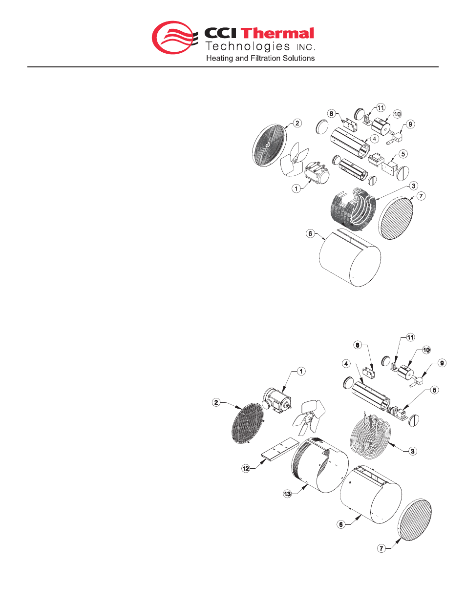
Figure 1B - Large Cabinet
XGB Unit Heater Components
Figure 1A - Small Cabinet
XGB Unit Heater Components
Recommended
Catalog Number
kW
Voltage
Max Line Amps
Fuse Size
(Amps)
1 Ш
3 Ш
1 Ш
3 Ш
XGB038T3B
3.75
208
1 9
1 1
2 5
1 5
240
1 7
1 0
2 5
1 5
480
-
6
-
1 0
600
-
5
-
1 0
XGB050T3B
5
208
2 5
1 5
3 5
2 0
240
2 2
1 3
3 0
2 0
480
-
7
-
1 0
600
-
6
-
1 0
XGB075T3A
7.5
208
3 7
2 2
5 0
3 0
240
3 2
1 9
4 0
2 5
480
-
1 0
-
1 5
600
-
8
-
1 0
XGB100T2C
1 0
208
2 9
4 0
240
4 3
2 5
6 0
3 5
480
-
1 3
-
2 0
600
-
1 1
-
1 5
XGB100T3B
1 0
208
-
3 0
-
4 0
240
4 7
2 6
6 0
3 5
480
-
1 3
-
2 0
600
-
1 1
-
1 5
XGB150T3B
1 5
208
-
4 4
-
6 0
240
-
3 8
-
5 0
480
-
1 9
-
2 5
600
-
1 5
-
2 0
XGB200T3B
2 0
480
-
2 5
-
3 5
600
-
2 0
-
2 5
XGB225T3A
22.5
480
-
2 8
-
3 5
600
-
2 3
-
3 0
XGB250T2D
2 5
480
-
3 1
-
4 0
600
-
2 5
-
3 5
XGB300T2D
3 0
480
-
3 7
-
5 0
600
-
3 0
-
4 0
XGB325T2D
32.5
480
-
4 0
-
5 0
600
-
3 2
-
4 0
XGB350T2C
3 5
480
-
4 3
-
6 0
600
-
3 4
-
4 5
A
B
C
D1
D2
Weight
lbs (kg)
Small
16-7/8
8-7/8
25-3-/16 17-1/2
-
100
Cabinet
(429)
(225)
(640)
(445)
(45)
10-15 kW
Large
20-1/8
8-7/8
29-1/4
-
31-1/4 145 (66)
Cabinet
(511)
(225)
(743)
(794) 20-35 kW
185 (84)
STANDARD FEATURES, SMALL CABINET UNIT:
1) 1/12 hp explosion-proof motor
2) Inlet guard
3) Extra heavy wall tubular steel finned heating elements with
nickel plated finish
4) Patented
x-Max
®
explosion-proof terminal housing
5) 120V control circuit includes:
• Derated magnetic contactor
• Dual automatic reset high limits
• Transformer
6) Heavy duty 16 ga. stainless steel casing
7) Outlet louver assembly
8) Swivel bracket
9) Factory installed conduit seal
10) Supply connection housing
11) Terminal block for supply wiring and thermostat connection
STANDARD FEATURES, LARGE CABINET UNIT:
1) 1/2 hp explosion-proof motor
2) Inlet wire guard
3) Extra heavy wall tubular steel finned heating elements with
nickel plated finish
4) Patented
x-Max
®
explosion-proof terminal housing
5) 120V control circuit includes:
• Derated magnetic contactor
• Dual automatic reset high limits
• Transformer
• Fan delay relay
• Control fuse
6) Heavy duty 16 ga. stainless steel casing
7) Outlet louver assembly
8) Swivel bracket
9) Factory installed conduit seal
10) Supply connection housing
11) Terminal block for supply wiring and thermostat connection
12) Motor mount
13) Motor mount casing
Figure 1B - Large Cabinet XGB Unit Heater Components
Figure 1A - Small Cabinet XGB Unit Heater Components
Part No. 11110 - Rev. 02