Rs-485 option – VICI Two Position Microelectric User Manual
Page 6
®
®
North America, South America, and Australia/Oceania contact:
Europe, Asia, and Africa contact:
Valco Instruments Co. Inc.
VICI AG International
Cheminert
®
and VICI
®
are registered trademarks of Valco Instruments Co. Inc. and VICI AG
P.O. Box 55603
Houston, TX 77255
Sales: (800) 367-8424
Tech: (713) 688-9345
Fax:
(713) 688-8106 [email protected]
Parkstrasse 2
CH-6214 Schenkon
Switzerland
Phone: +41 41 925 6200
Fax:
+41 41 925 6201 [email protected]
TN-413 Rev 1/11
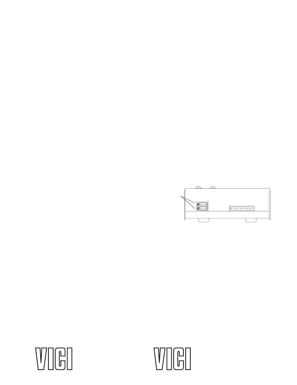
JUMPERS
1 AND 2
To set the ID of an actuator, connect it to an RS-232 serial port as shown in Figure 1 on
page 2.
Caution: When installing or replacing actuators on a shared serial port, make sure that no
two devices have been set to the same ID number.
1. Remove all of the actuators from the serial daisy chain except the one for which you are setting the ID.
2. Type VR
communication with the actuator is established. If there is no response, type *VR
if the ID is already set. If there is still no response, check the cabling and connections.
3. To
set an ID, type IDn
To
change an ID, type i
ID
n
is the current ID and
n is the new ID.
To
disable the ID feature, type i
ID*
i
is the current ID.
Setting a New Baud Rate
To permanently set a new baud rate for the actuator:
1. Establish communications with the actuator at the current baud rate.
2. Issue the command SB
nnnn to temporarily change the baud rate to the desired rate. If the power
goes down at this point, the baud rate will revert to the last permanent setting.
3. Change the host computer to the same baud rate just set in the actuator, and verify that you can
establish communications.
4. Re-issue the same SB
nnnn command you did previously (in Step 2), and the current baud will be
made permanent.
RS-485 Option
Software
The RS-485 option involves three minor software adapta-
tions to the RS-232 protocol. The first is that the ID range is
extended to include the characters “A” through “Z”, with
upper and lower cases treated as the same ID. The second
change is that the ID is required (either numbers from 0 to 9
or letters from A to Z), and must be included in all commands. The factory-set default ID for all devices
is “Z”. The third adaptation is that all commands must include a forward slash [/] as the start-of-
message character.
Hardware
The RS-485 hardware includes two 3-pin connectors (Figure 3) used as in/out connectors for easy
daisy-chaining of additional devices. Wired in parallel, the signal assignments are as follows: Pin 1 is
Ground, Pin 2 is Phase B, and Pin 3 is Phase A.
The four male pins in a vertical row to the left of these connectors are jumper headers, used to add
or remove terminating resistors from the communication lines. The top two and the bottom two should
be jumpered when term-ination is required. The RS-485 hardware specifications require termination at
each end of the communication line, so in a daisy-chaining application the jumpers should be removed
from all the intermediate devices. The RS-485 port on the host computer or controlling device generally
includes terminating resistors, so only the actuator on the end of the communication string needs to
have the jumpers installed.
Figure 3: Control module,