Serial control of the actuator, Establishing serial communications, Serial communication protocol – VICI Two Position Microelectric User Manual
Page 4
4
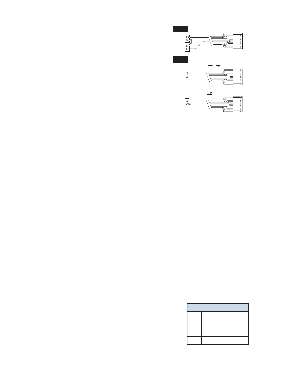
Position B. Operation in this mode requires two relays, as shown in
the illustration at right. Relays should be asserted (turned on) for
a minimum of 30 msec and deasserted (turned off) for a minimum
of 30 msec before the next assertion.
Mode 2
Operation in this mode requires one relay. In mode 2, asserting
pin 5 causes the actuator to toggle from the current to the oppo-
site position. Asserting pin 6 causes the actuator to toggle to the
opposite position, delay for a preset period of time (the default is
100 ms), and toggle back to the original position.
Mode Setup
To set the actuator mode, connect it to an RS-232 serial port as
described in the section below, Establishing Serial
Communications. To see the current setting, enter the SM
command as shown in the Serial Commands chart on page 5. To
change the mode, enter SM
n, where n is 1 or 2. The DT command displays the current delay time
setting. This setting can be changed with the DTn command, where
n is the desired time from 0 to
65,000 milliseconds.
Mode settings are saved when the power is off.
Serial Control of the Actuator
Establishing Serial Communications
Items required:
• Valco cable assembly I-22697 or equivalent
• Terminal emulation or communication software such as QModem, ProComm, or
Windows
®
Terminal or HyperTerminal, running on a PC-compatible computer
1. Connect the I-22697 cable to the actuator as indicated in Figure 1, and set the serial port at 9600
baud, no parity, 8 data bits, 1 stop bit, no hardware or software handshaking.
2. With the software running, check the bi-directional communication link between the keyboard/moni-
tor of the computer and the serial port by typing VR
ID has not been set, a message similar to the following will appear on your monitor, giving the
program number and date of the actuator firmware.
I-PD-ETX88RXX (XX = revision number)
2 - Aug - 99
If there is no response, it is possible that the ID has already been set. To force a response from a
device with an unknown ID, type *VR
elicit a response from all devices on line, no matter what their ID is.
Programmer’s note: To permit multiple actuators to share the same computer serial port, the actuator
serial port output is deactivated when not in use. At the beginning of a message the first character
transmitted is sometimes lost due to a framing error. To avoid this, a NULL character (zero value byte) is
sent at the beginning of each message. Most terminal programs will ignore the NULL character, but custom
software may require a character trap to delete it.
Serial Communication Protocol
Serial communication is based on an ASCII string protocol. Carriage re-
turn (OD hex) characters parse the communications by defining the end
of each command. Line feed characters (OA hex) are ignored.
A three-pin connector is used for the RS-232 interface: pin assignments
are indicated at right. Software flow control (Xon/Xoff) and hardware hand-
shaking are not supported.
Serial Port (RS-232) Cable
Pin # Signal Description
1
Ground
2
Transmit to host
3
Receive from host
CABLE (I-22537)
PIN 1
PIN 5
PIN 6
RELAY 1
RELAY 2
CABLE (I-22537)
PIN 1
PIN 5
RELAY
CABLE (I-22537)
PIN 1
PIN 6
RELAY
Mode 1
Mode 2
Toggle setup (A B A)
Delay setup (A B)