321 input amplifier, 322 set point selectors and d/a converter – VICI ITC User Manual
Page 7
It is readily seen that the ITC is responsible for maintaining the temperature within
the heated zone. However, proper selection and application of the thermocouple
and heater are essential if the ITC is to perform its function. (Refer to Section
2.2.)
1.32
ITC Block Diagram by Function
Almost any electronic device can be described by a block diagram of its circuit
elements, each element performing something essential to the function of the
device. Indeed, such a diagram is typically the first state in its design. Further,
devices of similar function will have similar block diagrams.
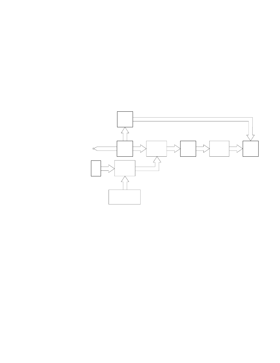
The function of the ITC is to control the temperature in a heated zone. A brief
discussion of what is required to perform the function reveals the elements
contained in its block diagram, Figure 3.
1.321
Input Amplifier
The signal supplied by the thermocouple is too small to be recognized by the other
circuit elements (approx. 50 microvolts/
o
C). Therefore, the signal must be amplified
to a useful level.
1.322
Set Point Selectors and D/A Converter
The thumbwheel switches provide a means of representing the desired tempera-
ture within the heated zone. (This temperature is hereafter referred to as the
setpoint.) The switches provide a digital representation of the setpoint, which is
then converted to a more useful signal by means of a ten-bit D/A converter. The
D/A converter conforms to the same transfer function as the input amplifier; i.e., a
representation of 100
°
C by the input amplifier is identical to the D/A converter’s
representation of 100
o
C.
DIFFERENTIAL
COMPARATOR
INPUT
AMP
TCPL
BREAK DE-
TECTION
POWER
ATTENUATOR
SET POINT
SELECT
D/A
CONVERTER
PROPORTIONAL
POWER
CONTROL
SENSOR
Are these blocks supposed
to correlate to items in
1.321 and following? No-
menclature needs to be
consistent. RC
HEATER
POWER
SWITCH
ZERO
CROSSING
SWITCH
Figure 3
5