Operation, 1 physical layout of the itc – VICI ITC User Manual
Page 12
2.
OPERATION
In this section practical considerations for the ITC’s usage are discussed.
2.1 Physical layout of the ITC
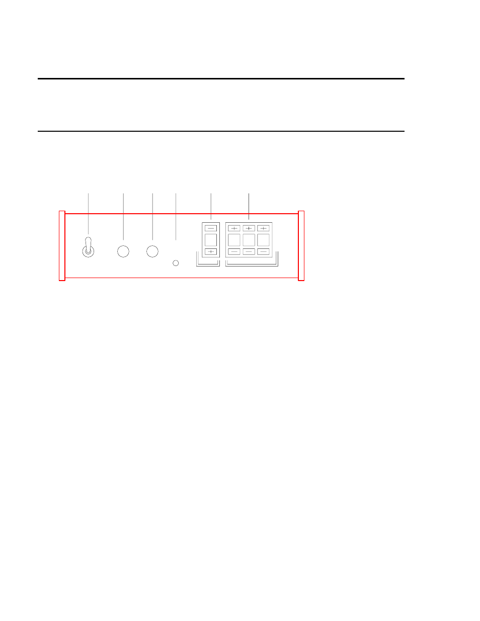
Following are illustrations of the various models of the Instrumentation Temperature
Controller. Figure 5 shows the front panel, and Figure 6 shows the top view of
the ITC. Figures 7 and 8 show the back panels of the 110V AC and 220V AC
models. The numbers on the illustrations relate to the numbered parts below.
1
Power Switch PWR
Front mounted toggle switch controlling power to heater and power supply
circuits.
2
Power On Indicator
Front mounted neon indicator; illuminated whenever the power switch is in
the ON position and power supply fuse is intact.
3
Heater Power On
Front mounted neon indicator; illuminated whenever instrument applies
power to heater; will not illuminate if heater is not connected, or if broken
thermocouple is detected.
4
Thermocouple Fault Indicator
Front mounted LED indicator; lights whenever thermocouple circuit is
broken.
5
Heater Power Attenuation Switch
Front panel mounted bidirectional ATTN switch; denotes heater power
attenuation in increments of 10 percent.
6
Setpoint Switches
Front panel mounted switches; denote controlled temperature setpoint in
o
C.
7
Calibration Adjustments
Printed circuit board mounted pots; DO NOT attempt adjustment.
1
2
3
4
5
6
OPEN
TCPL
5
9
9
9
PWR
ON
HTR
A
T
T
N
S
E
T
°
C
Figure 5: Front panel, model ITC10
10