Wiring, Installation – tekmar 003 Relay User Manual
Page 2
2 of 4
© 2011
D 003 - 05/11
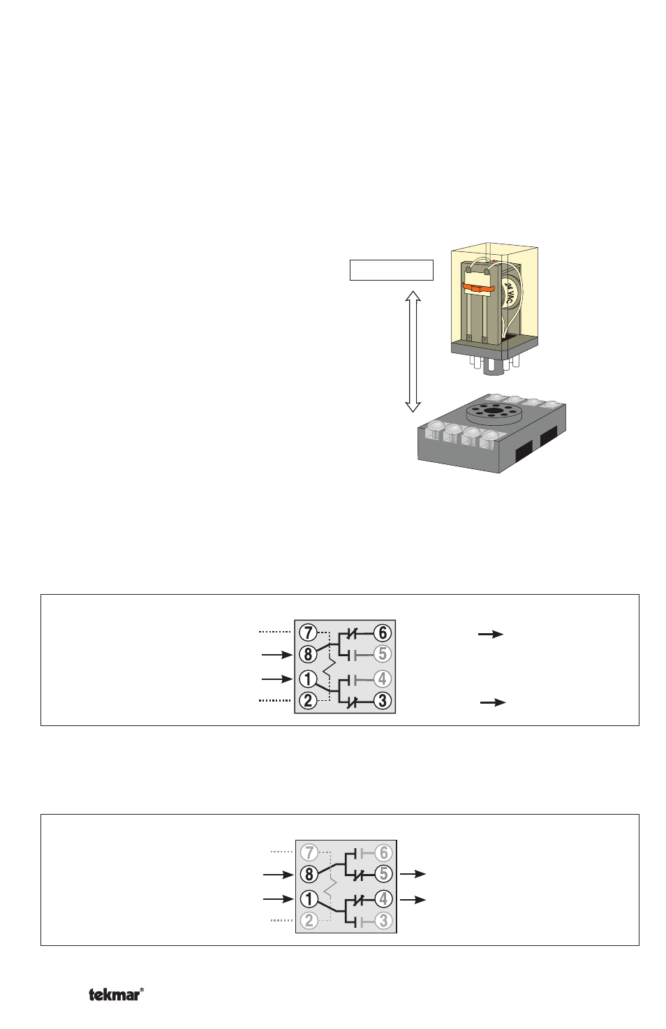
When 24 V (ac) is applied to the relay coil (terminals 2 and 7), the N.O. (Normally
Open) contacts will close and at the same time the N.C. (Normally Closed) contacts
will open. Also, the red LED indicator light on the top of the relay will turn on.
Coil powered with 24 V (ac)
Power Out
No Power
No Power
Power Out
Relay Coil POWERED
Relay Coil POWERED
Switching Power In
Switching Power In
Wiring
Power Out
No Power
No Power
Power Out
Relay Coil NOT POWERED
Switching Power In
Switching Power In
Relay Coil NOT POWERED
Coil with no power
When voltage is removed from the relay coil (terminals 2 and 7) , the spring will
automatically return the relay contacts to the normal (un-powered) position, and
the LED indicator will turn off.
Installation
The Relay base can be mounted directly to a flat surface, or onto a standard
TS35 DIN rail. Follow local codes for installation of the relay and wiring. For
class 2 circuits, no enclosure is required. For all other circuits, the relay should
be mounted in an approved enclosure.
Wiring connections are made at the base terminals and are checked with the
relay unplugged.
Relay pulls straight out of base. Base can
be pre-wired and wiring can be tested
before plugging in relay. Relay can be
replaced without disturbing the wiring.
Removable