tekmar 481 User Switch Installation User Manual
Page 9
9 of 12
© 2009
D 481 - 07/09
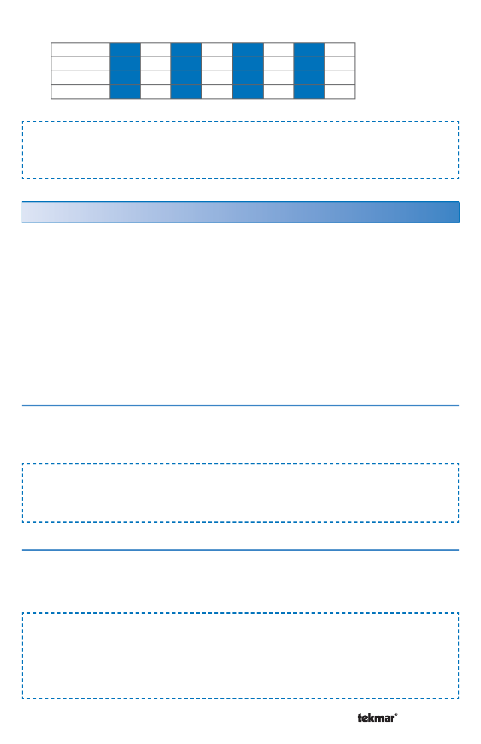
Application Example:
The relay contact can connect to a third party automation system to indicate the
current tN4 scene.
Scene
1
2
3
4
5
6
7
8
Contact 1
Off
On
Off
On
Off
On
Off
On
Contact 2
Off
Off
On
On
Off
Off
On
On
Contact 3
Off
Off
Off
Off
On
On
On
On
Multiple User Switches 480 and 481 can be used together when:
1) Applications require more than 3 User Buttons.
2) Applications require both input demands and output relay contacts.
3) User Switches with the same functionality are required at different locations.
Each tN4 bus cannot exceed 24 devices. Devices include Thermostats, Setpoint
Controls, Mixing Expansion Modules, and User Switches.
When using multiple User Switches at the same location, they can be installed
adjacent to each other in the same switch box.
Applications requiring more than 3 User Buttons
When more than 3 User Buttons are required, two or more User Switches can be
located next to each other in a double switch box. Each button can be programmed
to either select a scene or provide a setpoint enable.
Application Example:
Applications that select more than three scenes or setpoint device enables will
require two or more User Switches.
Applications with both input demands and output relay contacts
Applications that require input demands and output relay contacts require a 480
and a 481. The 480 provides the input demands and the 481 provides the output
contacts.
Application Example:
A third party telephone switch device allows a user to change the scene from 1
to 2 (Away) through the demand input on the 480. Should a critical or non-critical
error occur on the tN4 system, a 481 can close an alert contact to allow a third
party telephone switch to page a service technician.
Applications Using Multiple 480 and 481 Together
Scene
Signals