Step 8—install the air line and inflation valve, Step 9— inflate and test, Step 10— completion – Rite-Ride 4190 User Manual
Page 4
CLAMP RINGS,
SPACER RING,
FACE PLATE
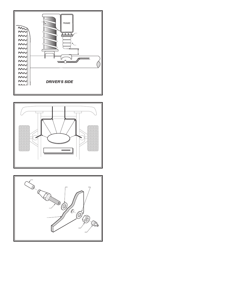
1/4”-3/8”
WORK-RITE
AXLE
COIL-RITE
Figure “E”
NYLON TIES
AIR LINE
REAR
BUMPER
AIR LINE
PUSH-TO-CONNECT
INFLATION VALVE
FLAT WASHER
HEX NUT
VALVE CAP
BODY OF
VEHICLE
Figure “F”
STEP 8—INSTALL THE AIR LINE AND
INFLATION VALVE
Select a location on the vehicle for the air inflation valves.
The location can be located on the bumper or the body
of the vehicle, as long as it is in a protected location so
the valve will not be damaged, but maintain accessibility
for the air chuck see Figure “E”. Drill a 5/16" hole and
install the air inflation valve using two 5/16" flat washers
per valve as supports see Figure “F”.
FOLLOW STEPS 1-8 FOR THE OTHER SIDE OF
THE VEHICLE.
STEP 9— INFLATE AND TEST
Inflate the air springs to recommended operating pres-
sure (see page 1 for operating pressures). With a soap
and water solution, check for air leaks around the fittings
and valve core. We recommend inflating and deflating
in 5 psi increments to find the ideal riding condition for
your vehicle.
STEP 10— COMPLETION
This now completes the installation. Install. Raise the
vehicle and remove the jack stands and lower the vehicle
back onto the ground. Inflate the Coil-Rite air helper
springs to 5 psi.
NOTE: Check air pressure on a monthly basis.
Figure “D”