Rite-Ride 4173 User Manual
Page 2
AIR LINE TO
INFLATION VALVE
Figure “B”
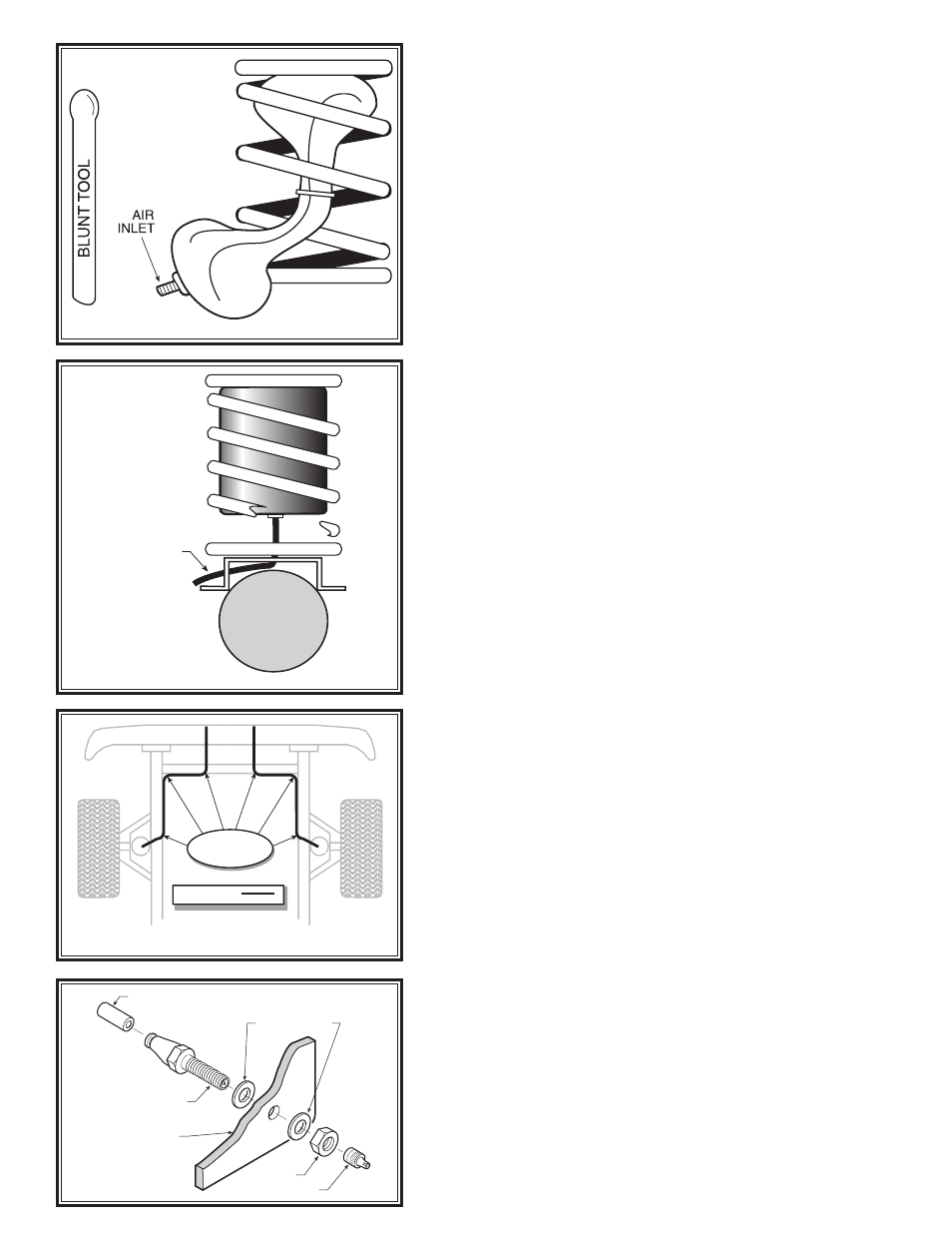
STEP 1— AIR SPRING PREPARATION
Remove the inflation valve cap from the inflation valve on
the air spring. Using the valve cap as a core tool from the
inflation valve, remove the inflation valve core from the air
spring. Exhaust the air spring by pushing it flat then re-insert
the valve core back into the air spring to keep it collapsed.
STEP 2—INSTALLING THE AIR SPRING
Insert the top of the flattened air spring into the coil spring
through the lowest opening with the inflation valve inlet at
the bottom as shown in Figure “A”.
STEP 3—ADJUSTING THE AIR SPRING
Push the air spring up into the coil spring by hand or with a
blunt tool. DO NOT use anything with sharp edges or corners
as this may damage the air spring.
When the air spring is completely within the coil spring,
remove the valve core to let the air back into the air spring.
Allow the air spring to return to its normal shape.
Install the spacer on top of the air spring. See Figure
“B”. Once the weight of the vehicle is applied to the sus-
pension aid the air springs are pressurized, the spacer will
stay in place.
STEP 4— REATTACH THE SHOCK ABSORBER
Attach shock absorbers if removed earlier in the installation.
Torque to manufactures specifications.
STEP 5— ROUTE THE AIR LINE
Cut the remaining air line tubing into two equal lengths (cut
the tubing as squarely as possible). Select a location for the
inflation valves in a protected area, such as the bumper or fuel
fill floor (
Note: The inflation valve will be installed in Step 6).
Insert the air line tubing into the push-to-connect fitting
on the air spring as far as possible. Route the tubing from
the air spring to the inflation valve, making sure to avoid
direct heat from the engine, exhaust pipe and away from
sharp edges. Secure with Nylon ties provided in your kit.
STEP 6—INSTALL THE AIR LINE AND INFLATION
VALVE
Select a location on the vehicle for the air inflation valves.
The location can be located on the bumper or the body of
the vehicle, as long as it is in a protected location so the
valve will not be damaged, but maintain accessibility for the
air chuck see Figure “C”. Drill a 5/16" hole and install the
air inflation valve using two 5/16" flat washers per valve as
supports see Figure “D”.
FOLLOW STEPS 1-6 FOR THE OTHER SIDE OF THE
VEHICLE.
STEP 9— INFLATE AND TEST
Inflate the air springs to recommended operating pressure
(see page 1 for operating pressures). With a soap and water
solution, check for air leaks around the fittings and valve core.
We recommend inflating and deflating in 5 psi increments to
find the ideal riding condition for your vehicle.
STEP 10— COMPLETION
This now completes the installation. Install. Raise the vehicle
and remove the jack stands and lower the vehicle back onto
the ground. Inflate the Coil-Rite air helper springs to 5 psi.
NOTE: Check air pressure on a monthly basis.
Figure “A”
Figure “C”
NYLON TIES
AIR LINE
REAR
BUMPER
AIR LINE
PUSH-TO-CONNECT
INFLATION VALVE
FLAT WASHER
HEX NUT
VALVE CAP
BODY OF
VEHICLE
Figure “D”