Rite-Ride 2474 User Manual
Page 3
7/16” HOLES TO BE DRILLED
UPPER
BRACKET
step 1 — prepare the vehIcle
Make sure that the vehicle is on a solid level surface. Take neces-
sary safety precautions such as using wheel chocks when working
under your vehicle. All illustrations are of the left, or driver’s side
of the vehicle. Follow the same procedures for installation on the
right, or passenger’s side.
step 2 — preassemble the rIde-rIte kIt
Select one upper bracket and one upper brace from the kit. Attach
the upper brace to the pair of holes in the middle of the upper
bracket using one 3/8"-16 x 1-1/2" hex bolt, one 3/8"-16 x 1 1/2"
flat head bolt, and two 3/8"-16 flange lock nuts as shown in
Figure
“A”. Select two air springs and attach them to the upper bracket
using the 3/8"-16 flange lock nuts. Align the studs on the air spring
with the holes on the upper bracket making sure the air inlets can
be seen through the large holes in the upper bracket,
see Figure
“A”. Install the elbow fittings into the air springs as shown in Fig-
ure “A”. Tighten the fittings securely to engage the orange thread
sealant. Point the elbow fittings towards the center of the upper
bracket.
Figure “A”. Select one lower bracket and fasten it to the
air helper springs using two 3/8"-16 x 5/8" flat head bolts.
See
Figure “A”.
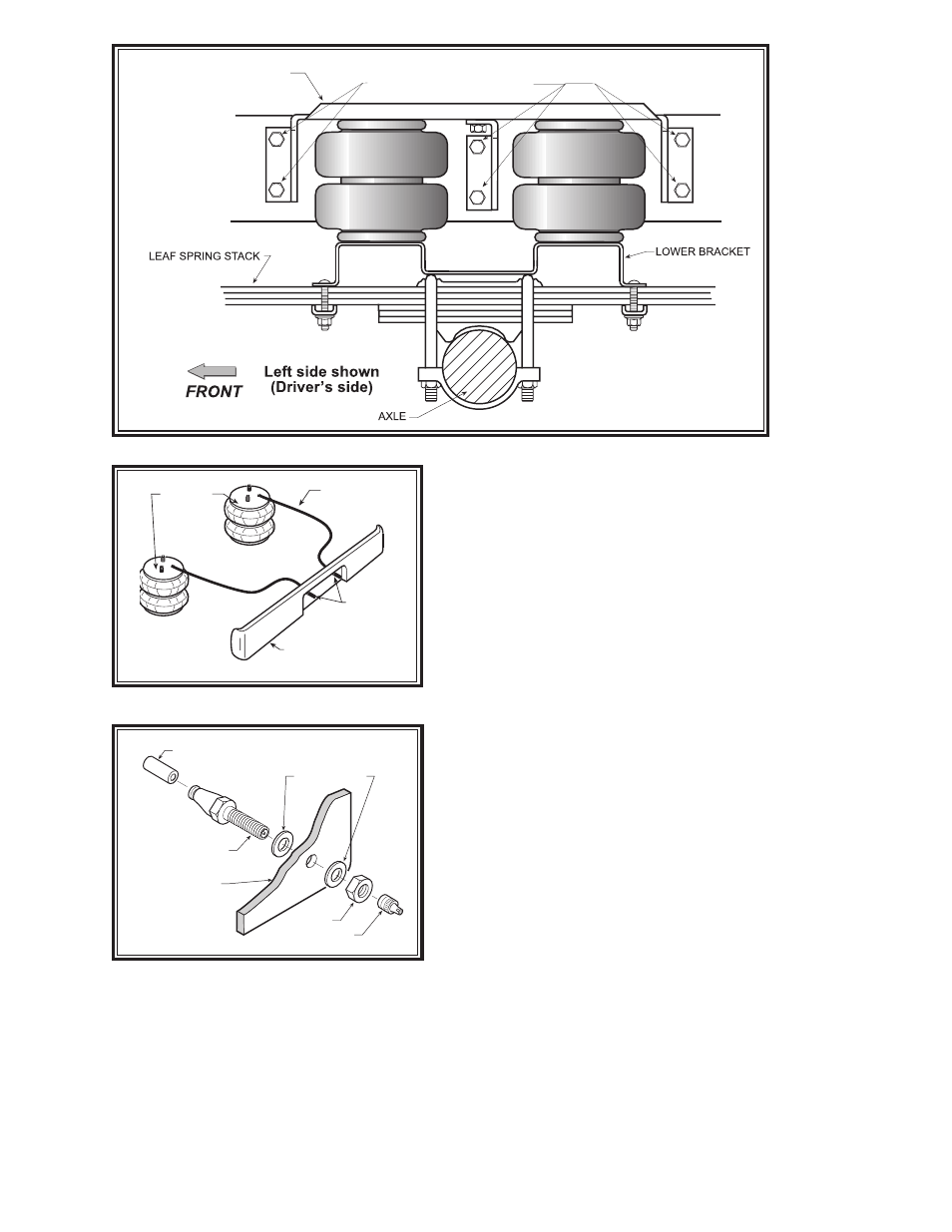
step 3 — upper bracket attachment
Position the assembly on the frame as shown in
Figure “A” &
“B”. Using the upper bracket as a template, mark the six mount-
ing holes with a center punch.
Before drilling the mounting holes
make sure all lines are cleared from the path of the drill. Dam-
age to lines can be avoided by inserting a piece of wood between
the frame rail and any lines in the path of the drill. Attach the upper
bracket to the frame as shown in
Figure “A” using the 3/8"-16 x
1-1/2" hex bolts, 3/8" washers, and 3/8"-16 flange lock nuts.
See
Figure “A” & “B”.
step 4 — loWer bracket attachment
With the assembly bolted to the frame, attach the lower bracket to
the leaf spring stack by installing four 3/8"-16 x 5" carriage bolts
in the square holes of the lower bracket. The lower bracket is then
secured by a bracket strap which is placed under the leaf spring
stack and retained with 3/8"-16 flanged lock nuts.
See Figure “A”
& “B”.
Figure “B”
AIR LINE
PUSH-TO-CONNECT
INFLATION VALVE
FLAT WASHER
HEX NUT
VALVE CAP
BODY OF
VEHICLE
Figure “D”
AIR HOSE
INFLATION
VALVES
BUMPER
AIR
SPRINGS
Figure “C”