Nstallation, Rocedure, 6 - i – Rite-Ride 4134 User Manual
Page 3: 7 - i, 8 - i, 9 - c
C
OIL
-R
ITE
I
NSTALLATION
P
ROCEDURE
NOTE: C
HECK
AIR
PRESSURE
ON
A
MONTHLY
BASIS
.
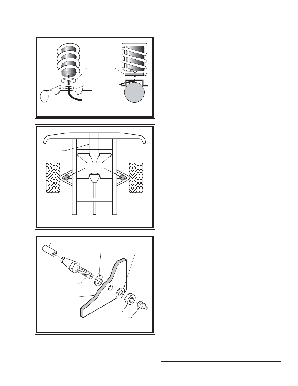
FIGURE "D"
FIGURE "E"
AIR SPRING
SUPPORT
FIGURE "F"
S
TEP
6 - I
NSTALL
THE
INFLATION
VALVE
Drill a 5/16" hole where you wish to mount the
inflation valve. Remember to keep the inflation valve in
a protected area that is easily accessible. Attach the
inflation valve to the bumper or body of the vehicle see
Figure "F".
Cut the excess air line tubing so that it will fit easily
into the inflation valve, making sure the end is cut
squarely (a "saw" cut with a sharp knife is preferred).
Push the end of the tubing into the inflation valve as far
as possible.
S
TEP
7 - I
NSTALL
THE
OPPOSITE
-
SIDE
AIR
SPRING
Follow Steps 2-6 to install the second air spring on
the remaining side of the vehicle.
S
TEP
8 - I
NFLATE
AND
TEST
Inflate the air springs to recommended maximum
operating pressure (see page 1 for operating pressures).
With a soap and water solution, check for air leaks
around the fittings and valve core. We recommend
inflating and deflating in 5 p.s.i. increments to find the
ideal riding condition for your vehicle.
S
TEP
9 - C
OMPLETION
This now completes the installation. Raise the
vehicle and remove the jack stands and lower the vehicle
to the ground. Re-attach the positive battery cable.
NYLON
TIES
AIR LINE
PUSH-TO-CONNECT
INFLATION VALVE
BODY OF
VEHICLE
AIR LINE
FLAT WASHER
HEX NUT
VALVE CAP