Rite-Ride 4192 User Manual
Page 2
STEP 1—VEHICLE PREPARATION
Remove the negative battery cable. With the vehicle on a solid level surface, chock the front wheels. Using a jack
rated for the weight of your vehicle, raise the wheels off the ground. Lower the vehicle frame onto jack stands rated
for the vehicle weight, making sure the suspension is fully extended. (Do not use wood or concrete blocks to support
the vehicle.) Your vehicle is equipped with jounce bumpers attached to the frame, inside the coil springs. Remove
the jounce bumpers by pulling down at an angle (The jounce bumpers will not be reused). Next, drill a 7/16" hole in
the jounce bumper mount in the anticipated direction of the air line,
see Figures “C”, “D”, & “E”.
STEP 2 — SHOCK ABSORBERS
If necessary, additional clearance between the coil windings may be obtained by removing the shock absorbers from
the lower mounts and lowering the suspension an additional one to two inches.
(CAUTION: Do not put tension or
strain on the flexible brake lines.)
STEP 3— AIR SPRING PREPARATION
Cut a two inch piece of air line tubing making sure the tubing is cut as square as possible (a “saw” cut with a sharp
knife is preferred). Install the tubing into the push-to-connect air inlet on the air spring. Exhaust the air from the air
spring by rolling it up towards the air inlet. After the air is exhausted, install the plug into the tubing coming out of
the air spring,
see Figure “A”.
STEP 4 — INSTALL THE AIR SPRING
Insert the top of the flattened air spring into the coil spring through the lowest opening in the coil spring with the
air inlet at the top of the coil spring,
see Figures “A”, “B”, & “D”. Push the air spring into the coil spring by hand
or with a blunt tool.
DO NOT use anything with sharp edges or corners, as damage may occur. When the air
spring is completely within the coil spring, remove the plug and allow the air spring to return to its normal shape.
Push the air spring to the bottom of the coil spring and insert the protector over the air line and onto the top of the
air spring. Install the union elbow on to the end of the air line.
See Figures “B” & “D”. For installation on the right
side, repeat Steps 2 through 4.
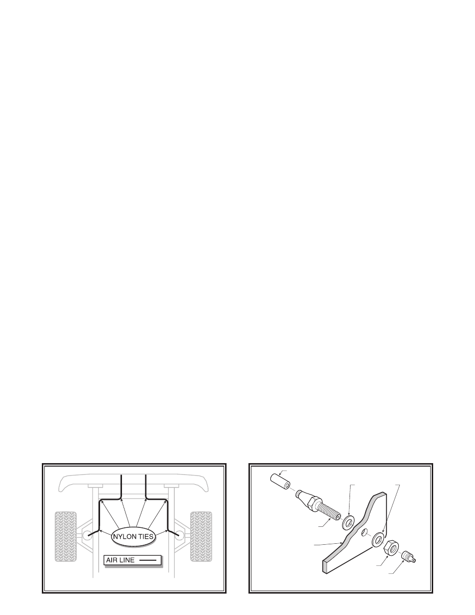
STEP 5— ROUTE THE AIR LINE
Select a location for the inflation valves in a protected area such as on the bumper or body. Use a sleeve protector
on the air line to protect the tubing where it passes through the jounce bumper mount. Route the air line from the
union elbow, through the 7/16” hole drilled in step 1, to the inflation valves
(Figure “E” & “F”). Avoid any sharp
edges or hot surfaces as well as sharp angles. The air line can be secured with the nylon ties provided. Install the
inflation valves into 5/16” holes,
see Figure “F”. Cut off any excess air line using the method mentioned above and
push the end as far as possible into the inflation valve.
STEP 7— INFLATE AND TEST
Inflate the air springs to recommended maximum operating pressure (see page 1 for operating pressures). With a
soap and water solution, check for air leaks around the fittings and valve core. Inflate and deflate in small increments
to find the ideal riding conditions for your vehicle.
STEP 8— COMPLETION
Re-attach the shocks if necessary and the wheels. Torque all nuts and lug nuts to manufacture’s specifications. Raise
the vehicle, remove the jack stands, and lower the vehicle to the ground. Reattach the battery cable.
AIR LINE
PUSH-TO-CONNECT
INFLATION VALVE
FLAT WASHER
HEX NUT
VALVE CAP
BODY OF
VEHICLE
FIGURE “E”
FIGURE “F”