Rite-Ride 4146 User Manual
Page 2
Step 1 – Vehicle Preparation
Remove the negative battery cable. With the vehicle on a solid level surface, chock the front wheels.
Using a jack rated for the weight of your vehicle, raise the wheels off the ground. Lower the vehicle frame onto
jack stands rated for the vehicle weight, making sure the suspension is fully extended. (Do not use wood or
concrete blocks to support the vehicle.)
Step 2 – Remove the Coil Spring
Put a jack under the axle on the left side of the vehicle. Remove the lower bolt from the shock absorber.
Lower the axle until the coil spring can be removed.
Caution: DO NOT put tension or strain on the flexible
brake line.
Remove the jounce bumper located in the coil spring. The jounce bumper will not be reused. Drill a
3/8" hole in the center of the jounce bumper mount for the air line to pass through.
See Figure “C”
.
Step 3 – Install the Air Spring
Deflate the Coil-Rite air spring and place it inside the coil spring with the air fitting pointing up. Next,
place the upper support on top of the Coil-Rite (
Figure “A” & “B”
). Cut the air line into to equal lengths,
making sure the ends are cut as squarely as possible (a “sawing” motion with a razor blade is preferred). Route
the air line through the box frame and out through the center of the jounce bumper retainer. Push one end of
the air line into the fitting on the air spring.
Step 4 – Reinstall the Coil Spring
Reinstall the coil spring with the Coil-Rite on the vehicle. Pass the excess air line through the hole
drilled into the jounce bumper retainer. Reattach the bottom of the shock absorber and tighten the bolt to
manufacturers’ specifications.
See Figure “D”
. Please see heat shield notice for installation of heat shield.
For installation on the right side, repeat Steps 2 through 5.
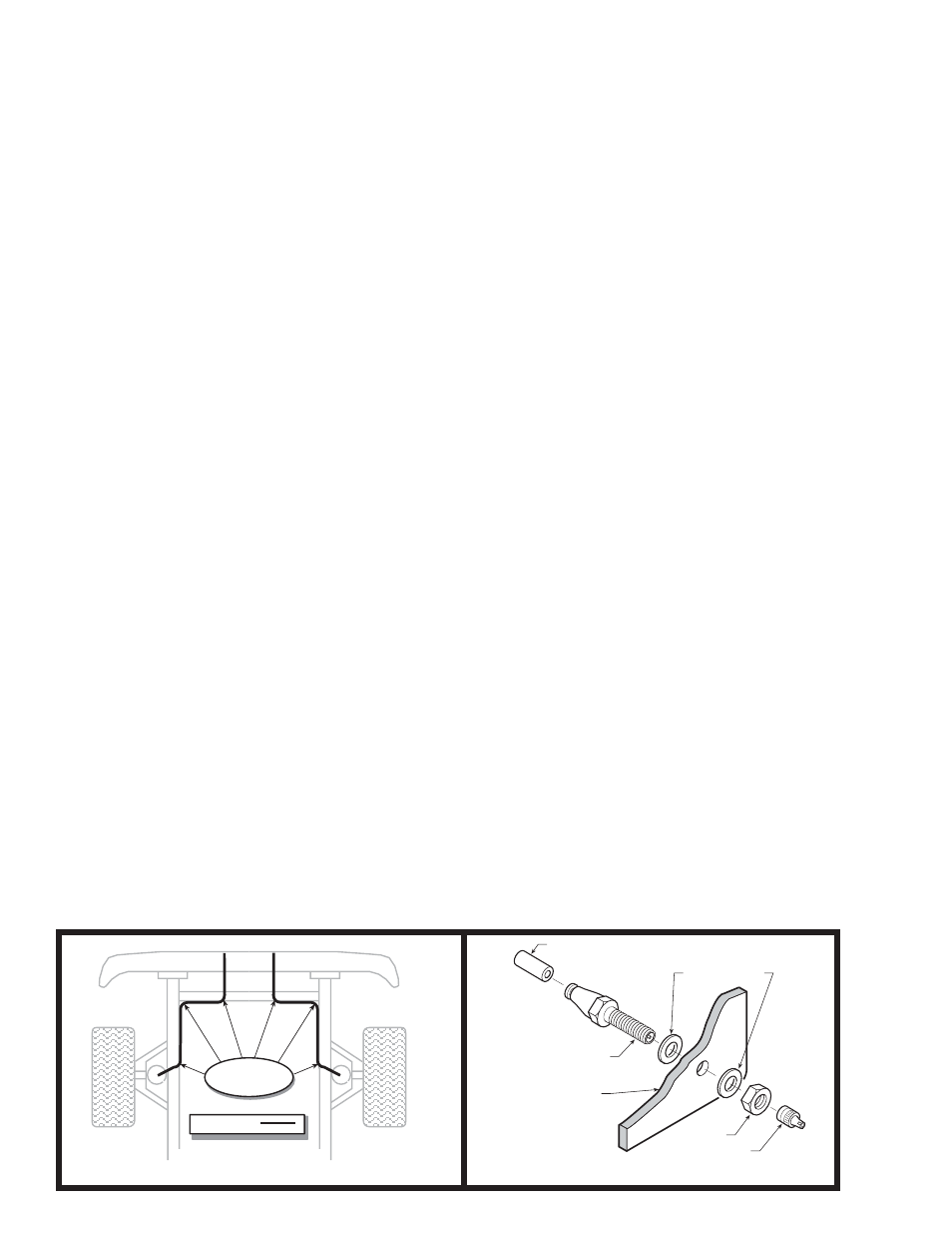
Step 5 – Install the Inflation Valves
Choose a location to mount the inflation valves, this should be a protected location such as the rear
bumper. Drill two 5/16" holes and pass the valves through and tighten the nuts.
See Figure “F”
.
Step 6 – Route the Air Line
Route the air line from the air springs to the inflation valves (
Figure “E”
). Avoid any sharp edges or
hot surfaces as well as sharp angles. The air line can be secured with the nylon ties provided. Cut off any
excess air line using the method mentioned above and push the end as far as possible into the inflation
valve.
Step 7 – Inflate and Test
Inflate the air springs to recommended maximum operating pressure (see page 1 for operating
pressures). With a soap and water solution, check for air leaks around the fittings and valve core. Inflate
and deflate in small increments to find the ideal riding conditions for your vehicle.
Step 8 – Completion
Raise the vehicle, remove the jack stands, and lower the vehicle to the ground. Reattach the
battery cable.
NYLON TIES
AIR LINE
AIR LINE
PUSH-TO-CONNECT
INFLATION VALVE
FLAT WASHER
HEX NUT
VALVE CAP
BODY OF
VEHICLE
Figure “E”
Figure “F”