Air line installation, Supports – Rite-Ride 4191 User Manual
Page 2
SUPPORTS
AIR LINE INSTALLATION
FIGURE “D”
PLEASE TAKE ALL NECESSARY
SAFETY PRECAUTIONS WHEN
INSTALLING YOUR COIL-RITE KIT.
NYLON TIES
AIR LINE
AIR LINE
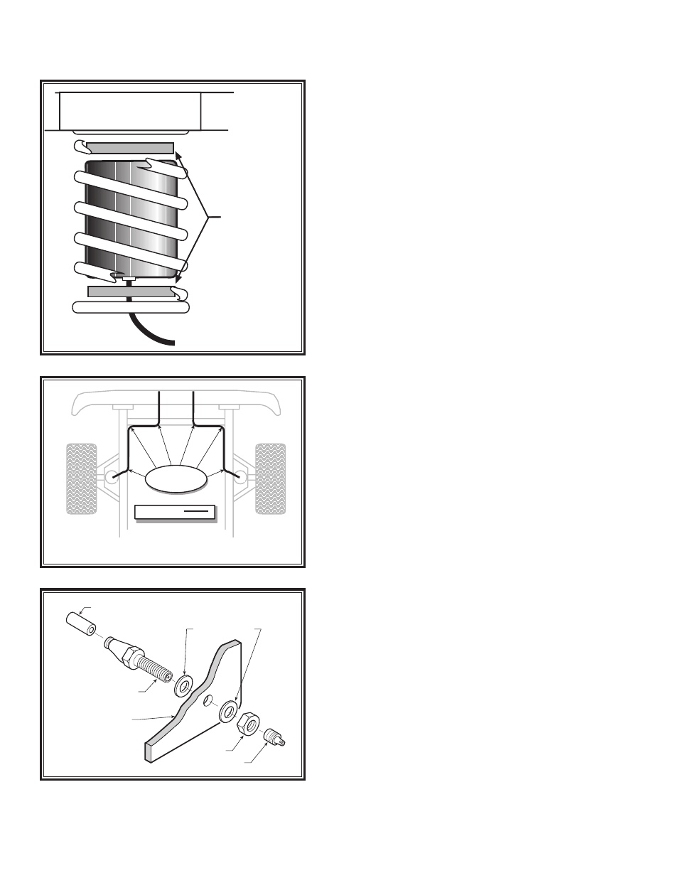
PUSH-TO-CONNECT
INFLATION VALVE
FLAT WASHER
HEX NUT
VALVE CAP
BODY OF
VEHICLE
FIGURE "E"
FIGURE “C”
STEP 5 — ROUTE THE AIR LINE
Cut the remaining air line tubing into two equal lengths
(cut the tubing as squarely as possible). Select a loca-
tion for the inflation valves in a protected area, such as
the bumper or trunk floor (Note: The inflation valve will
be installed in Step 6).
Insert the air line tubing into the push-to-connect fit-
ting on the air spring as far as possible. Route the tubing
from the air spring to the inflation valve, making sure
to avoid direct heat from the engine, exhaust pipe and
away from sharp edges. Secure with nylon ties provided
in your Coil-Rite kit.
STEP 6 — INSTALL THE AIR LINE AND
INFLATION VALVE
Select a location on the vehicle for the air inflation valves.
The location can be located on the bumper or the body
of the vehicle, as long as it is in a protected location so
the valve will not be damaged, but maintain accessibility
for the air chuck see Figure “D”. Drill a 5/16" hole and
install the air inflation valve using two 5/16" flat wash-
ers per valve as supports see Figure "E".
FOLLOW STEPS 1-6
FOR THE OTHER AIR SPRING.
STEP 7 — INFLATE AND TEST
Inflate the air springs to recommended operating pres-
sure (see page 1 for operating pressures). With a soap
and water solution, check for air leaks around the fittings
and valve core. We recommend inflating and deflating
in 5 p.s.i. increments to find the ideal riding condition for
your vehicle.
STEP — 8 COMPLETION
This now completes the installation. Install the wheels
and torque the lug nuts to the manufacturers specifica-
tions. Raise the vehicle and remove the jack stands and
lower the vehicle back onto the ground.
NOTE: Check air pressure on a monthly basis.