Rite-Ride 2476 User Manual
Page 3
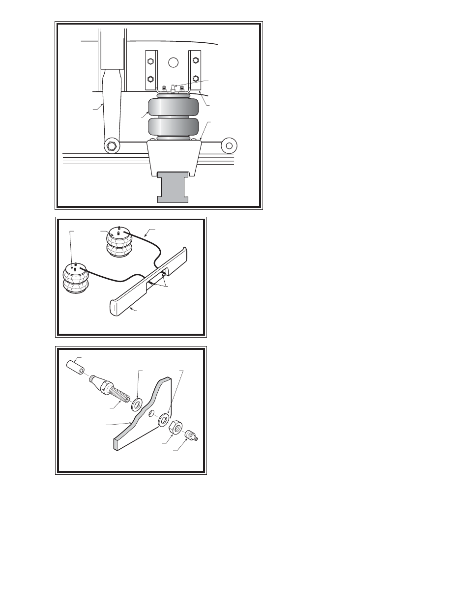
AIR
SPRING
FRAME
SHOCK
ABSORBER
LOWER
BRACKET
UPPER
BRACKET
AIR FITTING
S
TEP
1 - P
REPARE
THE
VEHICLE
With the vehicle on a solid, level surface chock
the rear wheels. Raise the vehicle by the front axle
and remove the front wheels. After the removal of
the wheels, lower the vehicle so that the axle rests
on jack stands rated for your vehicle's weight.
Remove the negative battery cable.
S
TEP
2 - P
RE
-
ASSEMBLE
THE
KIT
Pre-assembly will begin with the right, or
passenger's side of the vehicle. All illustrations
show the right side installation and assembly unless
noted otherwise.
Select one air spring from your kit. Install the air
fitting as shown in Figure "A". Tighten the air
fitting securely to engage the orange thread sealant.
Install the upper bracket by inserting the studs on the
top of the air spring into the smaller holes, see
Figure "A". Using two 3/8" -16 flanged hex nuts,
secure the upper bracket to the air spring.
Select one lower bracket and install the 3/8"-16x3-1/2" carriage
bolts into the square holes. Attach the lower bracket to the bottom of
the air spring using a 3/8" -16 x 3/4" flanged hex bolt. See Figure "A".
S
TEP
3 - I
NSTALL
THE
ASSEMBLY
TO
THE
VEHICLE
Place the assembly on top of the leaf stack centered over the axle.
The carriage bolts will pass through the holes in the shock mount, next
to the axle U-bolts. Slide the lower clamp bracket into place against
the U-bolts with the carriage bolts passing through the holes. Install
the 3/8-16 flange lock nuts onto the carriage bolts, securing the
assembly to the leaf stack. See Figure's "A" & "B".
Using the upper bracket as a template, mark and drill four 7/16"
holes into the frame. Attach the upper bracket to the frame with four
3/8"-16x1" hex bolts and flange lock nuts. See Figures "A" & "B".
S
TEP
4 - I
NSTALL
THE
PASSENGER
'
S
SIDE
ASSEMBLY
Follow steps 1 - 3 for the assembly and installation of the left, or
driver's side assembly.
S
TEP
5 - I
NSTALL
THE
AIR
LINE
AND
THE
INFLATION
VALVES
Uncoil the air line tubing and cut it into two equal lengths. DO NOT
FOLD OR KINK THE TUBING. Try to make the cut as square as
possible. Insert one end of the tubing into the fitting installed in the top
of the air helper spring. Push the tubing into the fitting as far as
possible see Figure "A".
Select a location on the vehicle for the air inflation valves. The
location can be on the bumper or the body of the vehicle, as long as it is in a protected location so the valve will not
be damaged, but maintain accessibility for the air chuck see Figure "C". Drill a 5/16" hole and install the air inflation
valve using two 5/16" flat washers per valve as supports see Figure "D". Run the tubing from the air helper spring
to the inflation valve, routing it to avoid direct heat from the engine, exhaust pipe, and away from sharp edges. Thermal
sleeves have been provided for these conditions. If a thermal sleeve is required, simply slide the sleeve over the air
line tubing to the location requiring protection. The air line tubing should not be bent or curved sharply, as it may buckle.
Secure the tubing to the vehicle with the nylon ties provided. Push the end of the air line tubing into the inflation valve
as far as possible see Figure "E".
S
TEP
7 - C
HECK
THE
AIR
SYSTEM
Figure "B"
Figure "D"
Figure "C"
AIR HOSE
INFLATION
VALVES
BUMPER
AIR
SPRINGS
AIR LINE
PUSH-TO-CONNECT
INFLATION VALVE
FLAT WASHER
HEX NUT
VALVE CAP
BODY OF
VEHICLE