1 - p, 2 - p, 3 - i – Rite-Ride 2070 User Manual
Page 3: 4 - i, 5 - i
N
OTE
:
Please read thorough this manual completely before installing
the air spring kit to your vehicle.
S
TEP
1 - P
REPARE
THE
VEHICLE
This kit can be installed without removing the front wheels.
Chock the wheels for safety before working under the vehicle.
S
TEP
2 - P
RE
-
ASSEMBLE
THE
KIT
Select one air helper spring and an upper bracket from your
kit. Insert the studs on the air spring in the mounting holes in the
upper bracket. Fasten the upper bracket to the air spring by
installing two 3/8"-16 flanged hex nuts on the air spring's studs.
Next, install the air fitting into the air spring. Tighten the air fitting
so as to make contact with the nylon ring and then tighten 1/2
turn to snug the fitting. No thread sealant is needed. Select one
lower bracket from you kit. Fasten the air spring to the lower
bracket using the two 3/8"-16 flanged hex bolt in the hole in the
lower bracket, see Figure "A".
S
TEP
3 - I
NSTALLING
THE
ASSEMBLY
TO
THE
VEHICLE
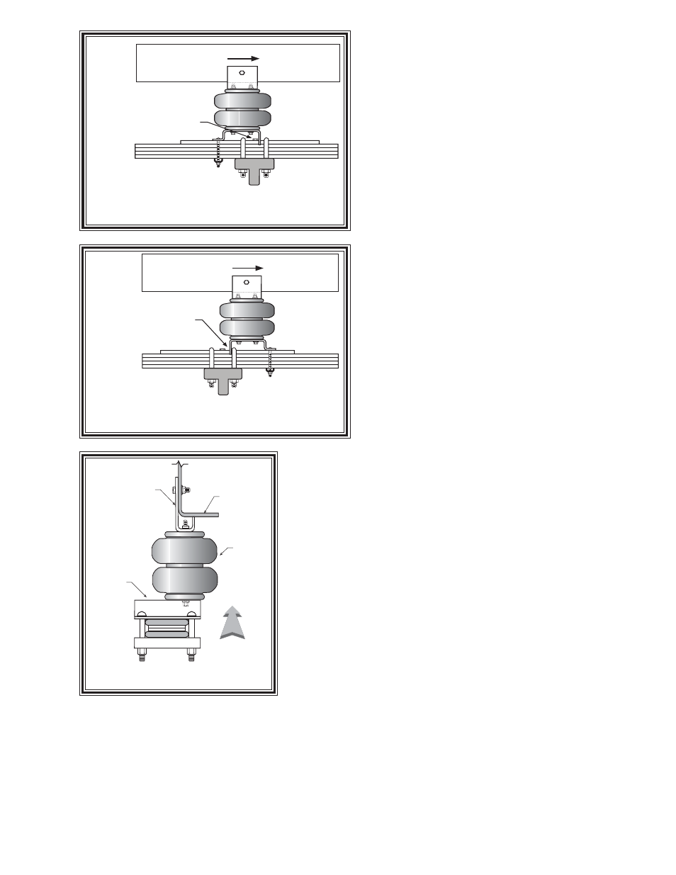
Place the assembly on the drivers side leaf stack. The lower
bracket will be butted up next to the bolt on the leaf between the
two retainers, see Figures "A", "B" & "C". Use the upper
bracket as a template to properly locate the hole. Drill the hole
in the side of the frame using a 3/8" drill. Before drilling any holes
make sure all electrical, brake and fuel lines are cleared from
the path of the drill bit. Damage to lines can be avoided by
inserting a piece of wood between the frame rail and any lines in
the path of the drill. Attach the upper bracket to the frame rail
using the 3/8"-16 x 1-1/2" bolt, 3/8" flat washer, and 3/8"- 16 flange nut. Next, insert
the 3/8"-16 x 3 1/2" carriage bolts through the square holes in the lower bracket.
The lower bracket should be aligned over the leaf spring, see Figure "B"& "C".
The carriage bolts should be straddling the leaf stack. Slide the bracket strap on
the carriage bolts and secure it with two 3/8"-16 flanged lock nuts, see Figure "A".
Once the assembly is in place, ensure that there is at least 1/2" of clearance around
the air spring.
S
TEP
4 - I
NSTALLATION
OF
THE
PASSENGER
'
S
SIDE
ASSEMBLY
Follow steps 1-3 with reverse orientations for assembly and installation of the
passenger's side assembly.
S
TEP
5 - I
NSTALL
THE
AIR
LINE
AND
INFLATION
VALVE
Uncoil the airline tubing and cut it into two equal lengths. DO NOT FOLD OR
KINK THE AIRLINE TUBING. Try to make the cut as square as possible. Insert
one end of the airline tubing into the air fitting installed in the top of the air helper
spring. Push the airline tubing into the fitting as far as possible. Select a location
on the vehicle for the air inflation valves. The location can be on the bumper or
the body of the vehicle, as long as it is in a protected location so the valve will not be damaged, but maintain accessibility for
the air chuck see Figure "E". Drill a 5/16" hole and install the air inflation valve using two 5/16" flat washers per valve as supports
see Figure "F". Run the airline tubing from the air helper spring to the valve, routing it to avoid direct heat from the engine, exhaust
pipe, and away from sharp edges. Thermal sleeves have been provided for these conditions. The airline tubing should not be
bent or curved sharply as it may buckle. Secure the airline tubing in place with the nylon ties provided. Push the end of the airline
tubing into the inflation valve as illustrated see Figure "F".
Figure "B"
Figure "D"
Figure "C"
FRONT
SET THE LOWER BRACKET
NEXT TO THE BOLT
AS SHOWN
ORIENTATION FOR 1990-2003
FRONT
SET THE LOWER BRACKET
NEXT TO THE U-BOLT
AS SHOWN
ORIENTATION FOR 2004-CURRENT
LOWER
BRACKET
UPPER BRACKET
AIR
SPRING
FRAME RAIL
FRONT