Rite-Ride 2558 User Manual
Page 3
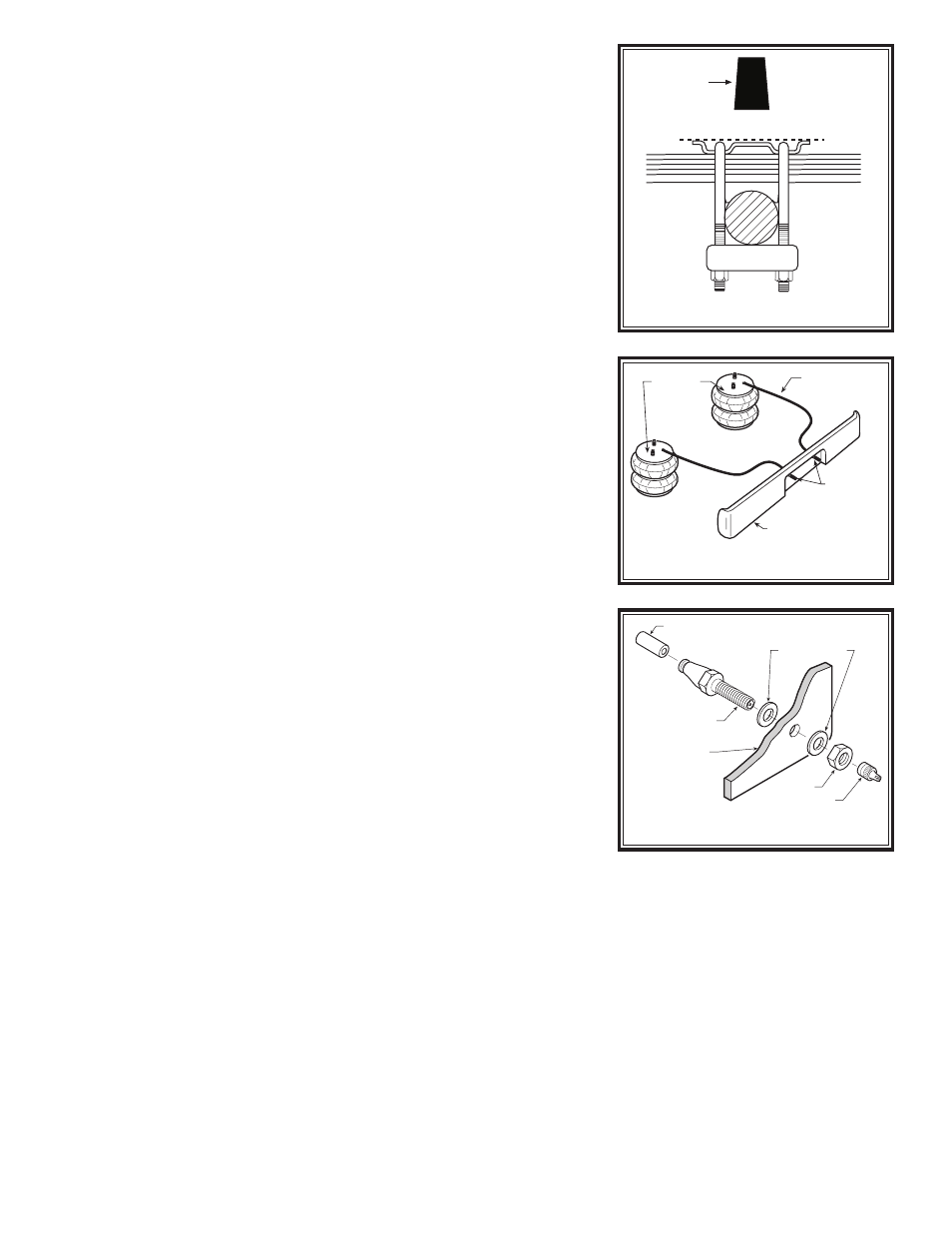
Figure “D”
STEP 1— PREPARE THE VEHICLE
Place the vehicle on a solid level surface. Take necessary safety pre-
cautions such as using wheel chocks when working under your vehicle.
Remove the jounce bumpers by cutting them off as close to the bracket
as possible as shown in Figure “B”.
STEP 2— PREASSEMBLE THE KIT
Select the left upper bracket and an air spring from your kit. Attach the
upper bracket to the air spring with a 5/8" nylock nut. Install the male
fitting into the air spring. Tighten the air fitting securely to engage the
orange thread sealant. No additional thread sealant is needed, (see
Figure “A”). Attach the lower bracket to the air spring using the 3/8"-16
x 3/4" hex bolt. Tighten the bolt making sure the bracket is in the correct
position (see Figure “A”).
STEP 3— INSTALL THE PREASSEMBLY TO THE VEHICLE
Place the preassembly on the leaf stack of the left side of the vehicle
as shown in Figure “A”. Attach the upper bracket directly beneath the
frame rail using the 3/8" - 16 x 3.6" bail clamps OR the 3/8"-16 x 4" bail
clamp (2008 and newer), and 3/8" lock nuts. Attach the lower bracket to
the leaf stack using the 5-1/2" carriage bolts, 3/8" lock nuts, and bracket
straps, (see Figure “A”).
Follow the same procedures as outlined in Steps 1 through 3 for
installing the right side of the vehicle.
STEP 4— INSTALL THE AIR LINE
Uncoil the air tubing and cut it into two equal lengths.
DO NOT FOLD
OR KINK THE TUBING. The air line tubing should not be bent or curved
sharply as it may buckle with age. Make the cut as square as possible.
Insert one end of the tubing into the elbow fitting installed in the top of
the air helper spring.
Select a location on the vehicle for the air inflation valves. The locations
can be on the bumper or the body of the vehicle but be sure that it is in a
protected location so the valve will not be damaged yet still be accessible
for the air chuck (see Figure “C”). Drill a 5/16" hole or use an existing
hole and install the air inflation valve using two 5/16" stainless steel flat
washers per valve as supports (see Figure “D”). Run the tubing from
the air spring to the inflation valve, routing it to avoid direct heat from the
muffler or tailpipe, and away from sharp edges. Tubing protectors have
been provided for these conditions. Push the end of the air line tubing
into the inflation valve as illustrated (see Figure “D”). Secure the tubing
in place with the nylon ties provided.
STEP 5— CHECK THE AIR SYSTEM
Once the inflation valves are installed, inflate the air springs and check
the fittings for air leaks with an applied solution of soap and water. If a
leak is detected at a tubing connection then check to make sure that the
tube is cut as square as possible and that it is pushed completely into the
fitting. The tubing can easily be removed from the fittings by pushing the
collar towards the body of the fitting and then pulling out the tube. If a leak
is detected where the fitting screws into the spring, screw the elbow into
the spring until the leak stops. Reinflate the air helper springs and check
for leaks as noted above. Further information on trouble-shooting can
be found in the General Operation Instruction book included with this kit.
This now completes the installation. Before proceeding, check once
again to be sure you have proper clearance around the bellows.
With a
load on your vehicle and the helper air springs inflated, you must
have at least 1/2" clearance around the bellows. As a general rule,
the Ride-Rite Air Helper Springs will support approximately 32 lbs. of load
for each p.s.i. of inflation pressure (per pair). For example, 50 P.S. I. of
inflation pressure will support a load of 1600 lbs. per pair of air helper
springs.
FOR BEST RIDE use only enough air pressure in the air helper
springs to level the vehicle when viewed from the side (front to rear).
This amount will vary depending on the load, location of load, condition
of existing suspension and personal preference.
Figure “B”
CUT LINE
JOUNCE
BUMPER
AIR HOSE
INFLATION
VALVES
BUMPER
AIR
SPRINGS
Figure “C”
AIR LINE
PUSH-TO-CONNECT
INFLATION VALVE
FLAT WASHER
HEX NUT
VALVE CAP
BODY OF
VEHICLE