Rite-Ride 2355 User Manual
Page 3
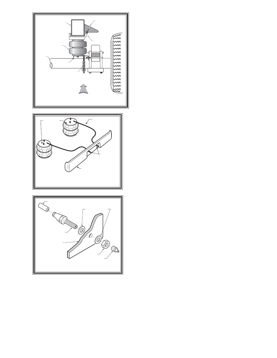
FIGURE "B"
FIGURE "C"
FIGURE "D"
NOTE:
Please read through this manual completely before installing
the air spring kit to your vehicle.
S
TEP
1
–
P
REPARE THE VEHICLE
With the vehicle on a solid, level surface chock the front
wheels. Remove the negative battery cable. Raise the vehicle by
the axle and remove the rear wheels. After the removal of the
wheels lower the vehicle so the axle rests on jack stands rated for
vehicles weight. Remove the negative battery cable.
S
TEP
2
–
P
RE-ASSEMBLE THE KIT
Select one air helper spring and one upper bracket from
your kit. Install the upper bracket to the air spring by inserting the
air helper spring studs into the holes, use two 3/8"-16 flange lock
nuts to secure the bracket to the air spring, see Figure “A”.
Install the air fitting as shown in Figure “A”. Tighten the air
fitting securely to engage the orange thread sealant. Position the
elbow so as to point in the anticipated location of the air inflation valve,
see Figures “A” and “C”. Fasten the lower bracket to the air
helper spring using a 3/8"-16 x 3/4” hex bolt, seeFigure “A”.
S
TEP
3
–
I
NSTALLING THE ASSEMBLY TO THE VEHICLE
Place the assembly on the driver’s side on top of the axle.
Attach the upper bracket to the jounce stop with the 5/16"-18 J-
bolt and 5/16"-18 hex nut. See Figures “A” and “B”. Next,
insert the nut-on-a-stick through the existing hole in the frame and
place it over the hole that is aligned with the hole in the upper
bracket. Insert a 3/8"-16 x 1" hex bolt through the bottom of the
upper bracket, through the frame rail, and into the nut-on-a-stick.
See Figure “A”. Attach the lower bracket to the axle using two
3/8"-16 x 7" carriage bolts, the axle bracket strap and 3/8"-16
flange lock nuts. Place the 4" wire loom over the rear carriage
bolt, see Figure “A". Be sure that the upper bracket and the
lower bracket are not pinching any lines, it may be necessary to
reposition some lines to avoid contact with the brackets. Install
the bail clamp from the outside of the leaf stack and into the holes
on the lower bracket. Secure the bail clamp with two 3/8"-16
flanged hex nuts. Once the assembly is in place, you must have a
minimum of 1/2” clearance around the air spring for proper
operation.
STEP 4 – INSTALLATION TO THE PASSENGER’S SIDE
ASSEMBLY
Reverse any orientations when assembling and installing the right, or passenger’s side of the vehicle.
S
TEP
5
–
I
NSTALL THE AIR LINE AND INFLATION VALVE
Uncoil the air line and cut it into two equal lengths. DO NOT FOLD OR KINK THE TUBING. Try
to make the cut as square as possible. Insert one end of the air line into the elbow fitting installed in the top of the
air helper spring. Push the tubing into the fitting as far as possible; see Figure “A”.
Select a location on the vehicle for the air inflation valves. The location can be on the bumper or the
bumper or the body of the vehicle, as long as it is in a protected location so the valve will not be damaged, but
maintain accessibility for the air chuck, see Figure “C”.
UPPER
BRACKET
FRAME RAIL
AIR
SPRING
LOWER
BRACKET
AXLE
DRIVER'S SIDE
REAR
NOTE: THE J-BOLT
HOOKS OVER THE
JOUNCE STOP
4 WIRE
LOOM
AIR HOSE
INFLATION
VALVES
BUMPER
AIR
SPRINGS
AIR LINE
PUSH-TO-CONNECT
INFLATION VALVE
FLAT WASHER
HEX NUT
VALVE CAP
BODY OF
VEHICLE