1 - p, 2 - p, 3 - i – Rite-Ride 2213 User Manual
Page 3: 4 - i, 5 - i
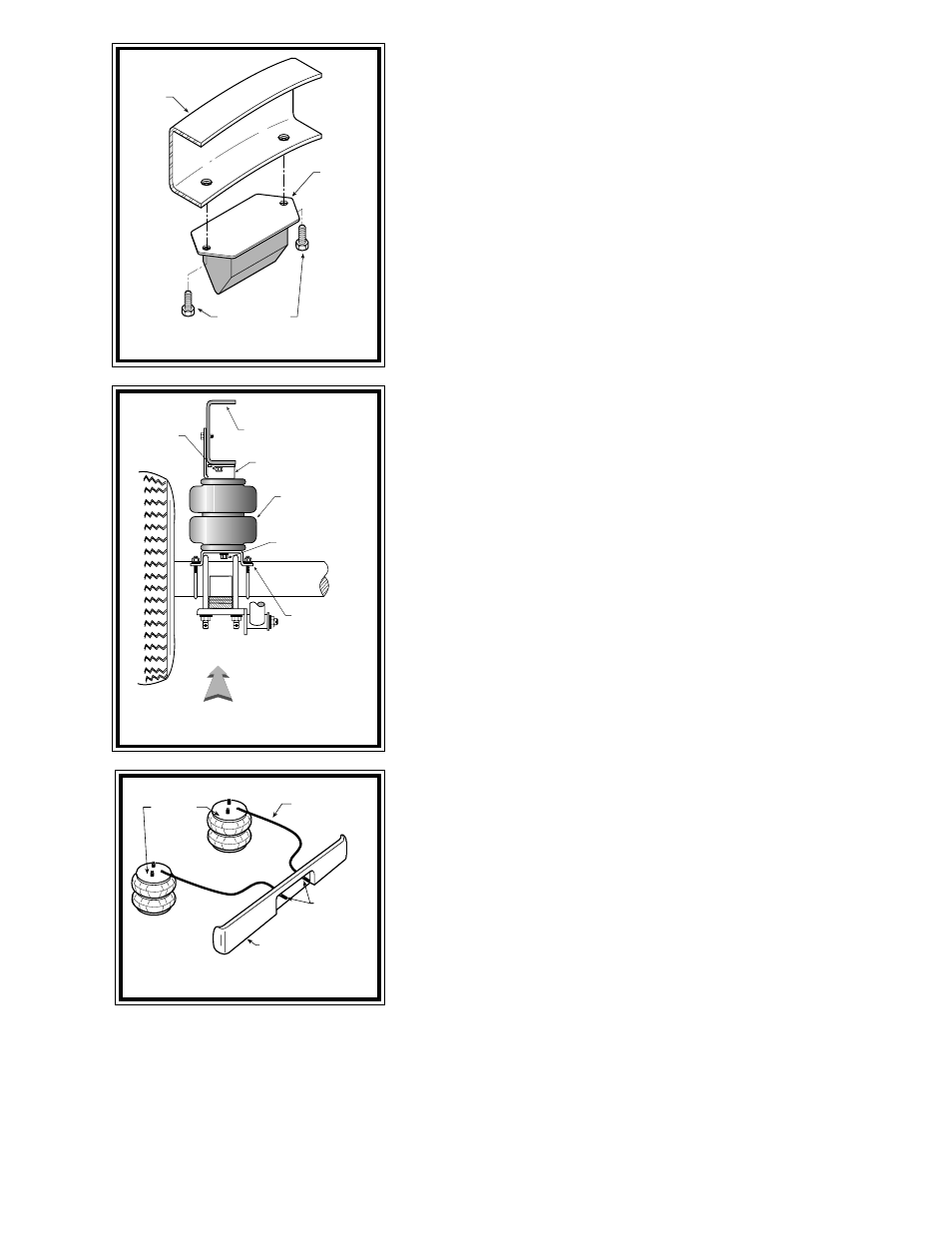
F
IGURE
"D"
F
IGURE
"C"
S
TEP
1 - P
REPARE
THE
VEHICLE
Remove the negative battery cable. With the vehicle on a solid, level surface
chock the front wheels. Raise the vehicle by the axle and remove the rear wheels.
After the removal of the wheels lower the vehicle so the axle rests on jack stands
rated to support your vehicles weight.
Your vehicle is equipped with rubber jounce bumpers. The bumpers are
attached to the frame directly above the axle. Remove these bumpers by unbolting
them from the bottom of the frame flange see Figure "B". This bumper will not be
reused with this kit. Do not discard the jounce bumper bolts, they will be used later
in this installation.
S
TEP
2 - P
RE
-
ASSEMBLE
THE
KIT
Pre-assembly will begin with the left (driver's) side of the vehicle. All pictures
show the installation on the left side of the vehicle unless noted otherwise. Select
an air spring and one upper bracket from your kit. Insert the studs on the air spring
into the mounting holes in the upper bracket, making sure the air inlet hole is visible
through the slot in the bracket. Secure the bracket to the air spring using two
3/8" -16 flanged lock nuts see Figure "A". Next, install the air fitting through the
slot in the upper bracket and into the air spring. Tighten the air fitting securely to
engage the orange thread sealant. Select a lower bracket from your kit. Align the
mounting slot in the lower bracket with the hole in the lower plate of the air spring.
Fasten the lower bracket to the air spring using a 3/8" -16 x 3/4" flanged hex bolt
(finger tight).
S
TEP
3 - I
NSTALL
THE
ASSEMBLY
TO
THE
VEHICLE
Position the air spring assembly on top of the axle housing so that slot in the
upper bracket is oriented toward the center of the vehicle while the vertical tab is
flush with the outside of the frame rail. It may be necessary to compress the air
spring assembly to properly position the upper bracket. Attach the horizontal tabs
on the upper bracket to the bottom of the frame rail using the bolts saved from the
removal of the jounce bumper see Figure "C". Secure the vertical tab to the outside
of the frame rail using two 1/4" -1" self-tapping screws. Drill two 1/8" pilot holes
in the frame rail, using the holes in the bracket as a template see Figure "A".
Vertically align the air spring and tighten the 3/8" -16 x 3/4" flanged hex bolt
securing the air spring to the lower bracket see Figure "C". Attach the lower bracket
to the axle housing using two U-bolts and four 5/16" -24 flanged hex nuts see Figure
"A". The lower bracket should fit on the axle housing without interfering with the
brake line. If the brake line is in contact with the lower bracket, it may be necessary
to move the brake line slightly by bending it away from the contact point.
S
TEP
4 - I
NSTALL
THE
PASSENGER
'
S
SIDE
ASSEMBLY
Reverse any orientations when assembling and installing the air spring on the
passenger's side of the vehicle.
S
TEP
5 - I
NSTALL
THE
AIR
LINE
AND
INFLATION
VALVE
Uncoil the air tubing and cut it in two equal lengths. DO NOT FOLD OR KINK
THE TUBING. Make the cut as square as possible. Insert one end of the tubing
into the push-to-connect elbow fitting installed in the top of the air helper spring
as far as possible.
Select a location on the vehicle for the air inflation valves. The location can be on the bumper or the body of the vehicle, as
long as it is in a protected location so the valve will not be damaged, but still maintain accessibility for the air chuck see Figure "D".
Drill a 5/16" hole and install the air inflation valve using two 5/16" flat washers per valve as supports see Figure "E". Run the tubing
from the air helper spring to the valve, routing it to avoid direct heat from the engine, exhaust pipe, and away from sharp edges.
Thermal sleeves have been provided for these conditions. The air line tubing should not be bent or curved sharply as it may buckle.
Secure the tubing in place with the nylon ties provided. Push the end of the air line tubing into the inflation valve see Figure "E".
F
IGURE
"B"
AIR HOSE
INFLATION
VALVES
BUMPER
AIR
SPRINGS
FRAME
JOUNCE
BUMPER
REMOVE AND
SAVE BOLTS
LOWER
BRACKET
DRIVER'S SIDE
FRONT
AIR
SPRING
UPPER
BRACKET
FRAME
RAIL
JOUNCE
BUMPER
BOLTS
TIGHTEN BOLT
AFTER ALIGNING
AIR SPRING