1 - p, 2 - p, 3 - i – Rite-Ride 2407 User Manual
Page 3: 4 - i, 5 - i
N
OTE
:
Please read thorough this manual completely before
installing the air spring kit to your vehicle.
S
TEP
1 - P
REPARE
THE
VEHICLE
With the vehicle on a solid, level surface chock the front
wheels. Remove the negative battery cable. Raise the
vehicle by the axle and remove the rear wheels. After the
removal of the wheels lower the vehicle so the axle rests on
jack stands rated for your vehicles weight. With a hack saw,
cut the jounce bumper located under the frame rail even
with the U-bolts, refer to Figures "A" and "B".
S
TEP
2 - P
RE
-
ASSEMBLE
THE
KIT
Select a lower bracket from the kit and one air helper spring from
your kit. Attach the lower bracket to the air spring using a 3/8-16 x
3/4" hex bolt, see Figure "A". Next, select an upper bracket and
the heat shield from the kit and install the heat shield between the upper
bracket and the air spring. See Figure "E". Attach the upper bracket
using 5/8" jam nut. Install the air fitting into the air spring. Tighten the air
fitting securely to engage the orange thread sealant, see Figure "A".
S
TEP
3 - I
NSTALLING
THE
ASSEMBLY
TO
THE
VEHICLE
Place the assembly on top of the leaf stack centered over the axle,
see Figure “A”. Attach the upper frame bracket to the upper bracket
with the four 3/8"-16 X 1" hex bolts and hex nuts. Be sure to position the
upper frame bracket so the large hole lines up over the large hole on the
frame. Install the 3/4”-16 x 1 3/4” hex head bolt, 3/4" washers, 3/4" lock
washer, and 3/4”-16 hex nut in the lager hole. Next, install the clamp
bracket over the jounce bumper brace and attach it to the upper bracket
with two 5/16"-18 X 1" hex bolts and nuts. See Figure "A". Once the
position of the upper bracket is fixed, place the 3/8"-16 X 3-1/2"
carriage bolts into the square holes in the lower bracket. Place the
bracket straps under the leaf spring and attach them to the carriage bolts
with the 3/8" flange lock nuts. See Figure "A".
S
TEP
4 - I
NSTALLATION
OF
THE
DRIVER
'
S
SIDE
ASSEMBLY
Follow steps 1-3 with reverse orientations for assembly and installation
of the drier's side assembly.
S
TEP
5 - I
NSTALL
THE
AIR
LINE
AND
INFLATION
VALVE
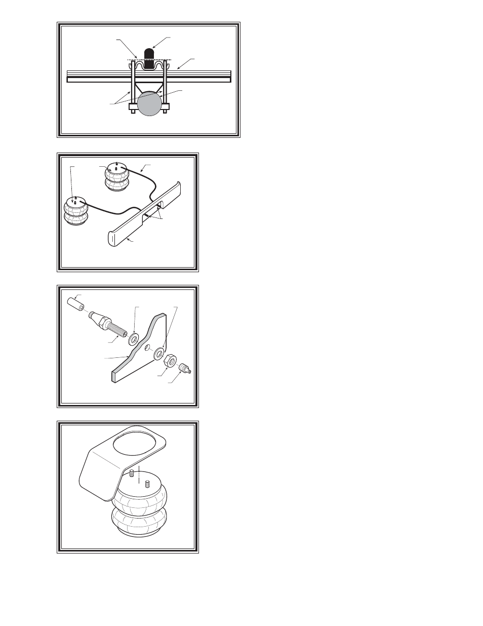
Uncoil the airline tubing and cut it into two equal lengths. DO NOT
FOLD OR KINK THE AIRLINE TUBING. Try to make the cut as
square as possible. Insert one end of the airline tubing into the air fitting
installed in the top of the air helper spring. Push the airline tubing into the
fitting as far as possible. Select a location on the vehicle for the air inflation
valves. The location can be on the bumper or the body of the vehicle, as long as it is in a protected location so the
valve will not be damaged, but maintain accessibility for the air chuck see Figure "C" on the next page. Drill
a 5/16" hole and install the air inflation valve using two 5/16" flat washers per valve as supports see Figure "D".
Figure "B"
Figure "C"
JOUNCE
BUMPER
AXLE
U-BOLTS
C U T
L I N E
LEAF STACK
AIR LINE
PUSH-TO-CONNECT
INFLATION VALVE
FLAT WASHER
HEX NUT
VALVE CAP
BODY OF
VEHICLE
Figure "D"
AIR HOSE
INFLATION
VALVES
BUMPER
AIR
SPRINGS
HEAT SHIELD
Figure "E"