Rite-Ride 2304 User Manual
Page 3
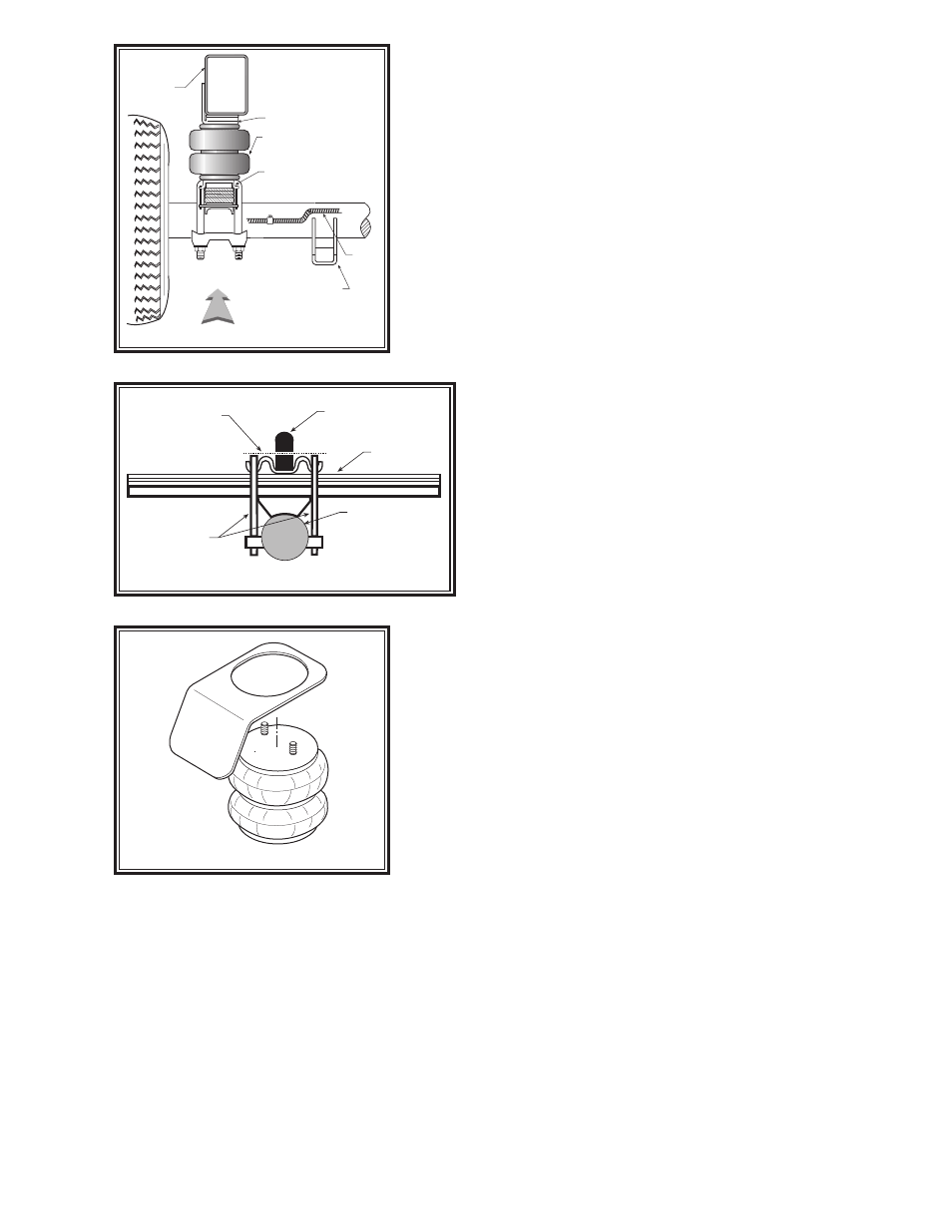
DRIVER'S SIDE
FROM REAR, LOOKING TO FRONT
UPPER
BRACKET
SHOCK
BRACKET
LOWER BRACKET
AIR SPRING
FRAME RAIL
BRAKE
LINE
NOTE:
Please read thorough this manual completely before installing the
air spring kit to your vehicle. A heat shield is required on the exhaust
side of the vehicle as noted in Step 4.
STEP 1— PREPARE THE VEHICLE
With the vehicle on a solid, level surface chock the front wheels. Remove
the negative battery cable. Raise the vehicle by the axle and remove the
rear wheels. After the removal of the wheels lower the vehicle so the axle
rests on jack stands rated for your vehicles weight. With a hack saw, cut
the jounce bumper located under the frame rail
even with the U-bolts,
refer to Figures “A” and “C”.
STEP 2— PRE-ASSEMBLE THE KIT
Select a lower bracket from the kit and place the 3/8"-16 x 3-1/2"car-
riage bolts into their designated holes. Select one air helper spring from
your kit. Attach the lower bracket to the air spring using a 3/8-16 x 3/4"
flange hex bolt,
see Figure “A”. Install the elbow fitting into the air spring.
Tighten the air fitting securely to engage the orange thread
sealant. Position the fitting to point to the anticipated location
of the air inflation valves,
see Figure “A” & “E”. Next, select
an upper bracket from the kit and bolt the upper bracket to the
air spring using 3/8"-16 flanged lock nuts.
Please note that a
heat shield is required on the exhaust side of the vehicle,
refer to Step 4.
STEP 3— INSTALLING THE ASSEMBLY TO THE
VEHICLE
Slide the flat bracket strap over the carriage bolts until it rests
against the lower bracket,
see Figure “A”. Place the assembly
on top of the leaf stack just behind the axle. Make sure that the
front of the bottom bracket is over the top of the axle u-bolt,
see Figure “A”. Once the position of the upper bracket is fixed,
mark the frame where the two holes will be drilled. Before drilling the
holes, make sure all electrical, brake and fuel lines are cleared from the
path of the drill. Damage to lines can be avoided by inserting a piece of
wood between the frame rail and any lines in the path of the drill. Drill
the 3/8" holes in the frame rail where marked. Finish attaching the upper
bracket to the frame rail using the provided 3/8"-16x 1" hex head bolts
and the 3/8"-16 nut plates. Next bolt the bracket strap beneath leaf stack
using the 3/8"-16 flange lock nuts.
STEP 4— INSTALLATION OF THE PASSENGER’S SIDE
ASSEMBLY
Follow steps 1-3 with reverse orientations for assembly and installation
of the passenger's side assembly.
Note: The use of a heat shield is
required on the passenger’s side of the vehicle, see Figure “D”. The
heat shield will mount between the upper bracket and the air helper
spring. Angle the heat shield so it will fall halfway between the air helper
spring and the closest point on the exhaust. Be sure that the heat shield will not contact any other component as
the suspension compresses (i.e. brake lines, shock absorbers, lower bracket assembly).
STEP 5— INSTALL THE AIR LINE AND INFLATION VALVE
Uncoil the airline tubing and cut it into two equal lengths. DO NOT FOLD OR KINK THE AIRLINE TUBING. Try to
make the cut as square as possible. Insert one end of the airline tubing into the air fitting installed in the top of the
air helper spring. Push the airline tubing into the fitting as far as possible. Select a location on the vehicle for the air
inflation valves. The location can be on the bumper or the body of the vehicle, as long as it is in a protected location
so the valve will not be damaged, but maintain accessibility for the air chuck
see Figure “E” on the next page. Drill
a 5/16" hole and install the air inflation valve using two 5/16" flat washers per valve as supports
see Figure “F”
on the next page. Run the airline tubing from the air helper spring to the valve, routing it to avoid direct heat from
the engine, exhaust pipe, and away from sharp edges. Thermal sleeves have been provided for these conditions.
The airline tubing should not be bent or curved sharply as it may buckle. Secure the airline tubing in place with the
nylon ties provided. Push the end of the airline tubing into the inflation valve as illustrated
see Figure “E”.
Figure “C”
HEAT SHIELD
Figure “D”
JOUNCE
BUMPER
AXLE
U-BOLTS
C U T
L I N E
LEAF STACK
Figure “B”